


Page 3
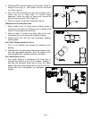
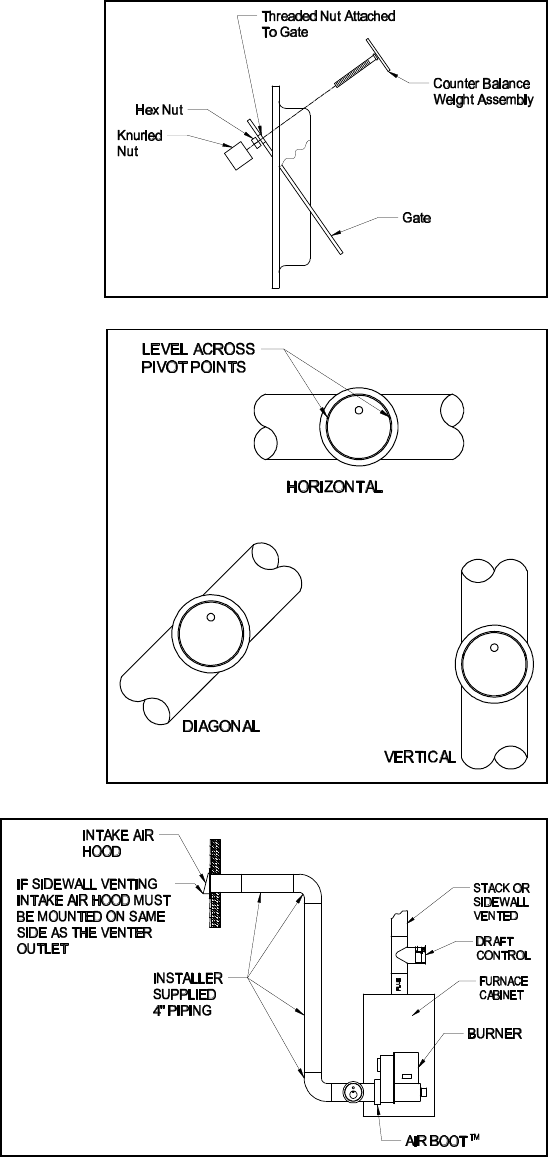
2. Assemble VRV balance weight onto the gate. Screw the
weight all the way in. Then attach lock nut and knurl
nut. (See Figure 3)
3. Mount the VRV assembly onto the tee and fasten with a
screw and nut in collar tabs. To ensure proper
operation, check the gate for being level across the
pivot points and plumb. (See Figure 4)
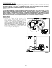
4. Refer to Figure 5 for general installation layout.
TERMINATION LOCATION GUIDELINES
1. Mount intake hood 12 inches above finished grade. If
mounting on the side of a building prone to drifting snow,
mount 12 inches above the snow line.
2. Mount at least 12 inches from either side of the vent
termination and on the same wall if sidewall venting.
3. Always mount with the inlet vent termination opening
pointing down.
INLET VENT TERMINATION INSTALLATION
1. Cut a 4-1/4” diameter hole through the sidewall of the
building.
2. Slide the inlet vent pipe through the hole and fasten to the
wall with appropriate fasteners. Seal the edges of the
mounting plate with a silicone sealant or equivalent.
DUCT WORK INSTALLATION
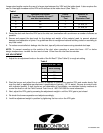
1. Duct length distance, a maximum of 30 linear feet of
standard duct pipe and two (2) 90° elbows. Subtract 7
feet from the maximum linear feet for every 90° elbow
added. Maximum linear footage will be less for flex duct.
Consult flex duct manufacturer for equivalent
lengths.
Figure 3
Figure 4
Figure 5