


10
NOTE: for Water Heaters in locations with high ambient temperatures (above
100°F or 38°C) and/or insufcient dilution air, it is recommended that CPVC
pipe and ttings marked ULC S636 compliant (MUST USE SUPPLIED VENT
TERMINAL) be used.
4. It is important that condensate not be allowed to buildup in the exhaust
vent pipe. To prevent this from happening the pipe should be installed
with a slight, 1/8" (3mm) per 5' (152 cm) of pipe maximum downward
(toward terminal) slope.
5. The vent system should be supported every 5' (152 cm) of vertical run
and every 3' (91cm) of horizontal run of vent pipe length.
NOTE: Stress levels in the pipe and ttings can be signicantly increased
by improper installation. If rigid pipe clamps are used to hold the pipe in
place, or if the pipe cannot move freely through a wall penetration, the
pipe may be directly stressed, or high thermal stresses may be formed
when the pipe heats up and expands. Install accordingly to minimize
such stresses.
VENT PIPE PREPARATION
1. INITIAL PREPARATION
A. Make sure the solvent cement you are planning to use is designed
for the specic application you are attempting.
B. Know the physical and chemical characteristics and limitations of
the PVC or CPVC piping materials that you are about to use.
C. Know the reputation of your pipe and cement manufacturer and
their products.
D. Know your own qualications or those of your contractor. The solvent
welding technique of joining PVC or CPVC pipe is a specialized skill
just as any other pipe tting technique.
E. Closely supervise the installation and inspect the nished job before
start-up.
F. Contact the manufacturer, supplier, or competent consulting agency
if you have any questions about the application or installation of
PVC or CPVC pipe.
G. Take the time and effort to do a professional job. Shortcuts will only
cause you problems and delays in start-up. The majority of failures
in these systems are the result of shortcuts and/or improper joining
techniques.
2. SELECTION OF MATERIALS
PRIMER
It is recommended that Tetrahydrofuran (THF) be used to prepare the surfaces
of pipe and ttings for solvent welding. Do not use water, rags, gasoline or
any other substitutes for cleaning PVC or CPVC surfaces. A chemical cleaner
such as MEK may be used.
CEMENT
The only cement approved for this system is IPEX System 636 CPVC Cement
Product for use on marked PVC and CPVC ULC S636 pipe and ttings.
SAFETY PRECAUTION: PRIMERS AND CEMENTS ARE EXTREMELY
FLAMMABLE AND MUST NOT BE STORED OR USED NEAR HEAT OR
OPEN FLAME. ALSO, USE ONLY IN A WELL-VENTILATED AREA.
INSTALLATION OF VENT SYSTEM
WARNING
THE OPTIONAL INTAKE VENTING ARRANGEMENT AND THE
EXHAUST VENTING ARRANGEMENT MUST BE INSTALLED TO
RUN DIRECTLY TO THE OUTDOORS AND NOT IN ANY WAY BE
CONNECTED TO ANOTHER VENTING SYSTEM (I.E. FURNACE,
DRYERS OR SPACE HEATERS). IT IS CRUCIAL THAT THE VENTING
ARRANGEMENT BE KEPT SEPARATE FROM OTHER VENTING
SYSTEMS. IF THIS WARNING IS IGNORED, AND THE SYSTEM IS
VENTED INCORRECTLY, IT MAY CAUSE IMPROPER OPERATION,
FIRE, EXPLOSION, OR ASPHYXIATION.
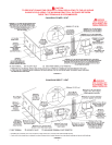
1. Plan the route of the vent system from the vent termination to the planned
location of the appliance. Layout the total vent system to use the minimum
of vent pipe and elbows possible.
2. The installer may add up to a MAXIMUM OF FIFTY (50) EQUIVALENT
FEET (15.2 m) of 3" pipe to the exhaust venting arrangement. This
addition of FIFTY (50) EQUIVALENT FEET (15.2 m) of pipe on both
the intake venting arrangement and exhaust venting arrangement must
include any 3" PVC elbows which equals (5) EQUIVALENT FEET (1.5
m) of pipe.
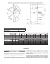
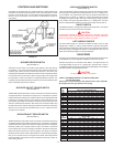
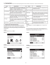
Table 2. VENT LENGTH TABLE
Number 3" 3" 4"
of 90° Minimum Maximum Maximum
Elbows Pipe (Ft./M.) Pipe (Ft./M.) Pipe (Ft./M.)
ONE (1) 7/2 45/13.7 115/35
TWO (2) 7/2 40/12.2 110/33.5
THREE (3) 7/2 35/10.7 105/32
FOUR (4) 7/2 30/9.1 100/30.5
FIVE (5) 7/2 --- 95/29
SIX (6) 7/2 --- 90/27.4
4" PVC may be used for a MAXIMUM intake of ONE HUNDRED TWENTY
(120) EQUIVALENT FEET (36.6m) and a MAXIMUM exhaust of ONE
HUNDRED TWENTY (120) EQUIVALENT FEET (36.6m). The maximum
number of 90° elbows with the 4" venting is six (6) on the intake and six (6)
on the exhaust. A 90° elbow is equal to ve (5) equivalent feet (1.5m) of pipe.
One (1) 90° elbow is equal to two (2) 45° elbows. Any venting conguration
using less than 50 equivalent feet should use 3" venting. See Table 2. For
either vent diameter, the maximum vent lengths in Table 2 are EXCLUSIVE
of the factory-installed vent component and prescribed terminations. That
is, the equivalent vent lengths associated with the 90° elbow (installed on
the unit) and the 45° termination elbow should NOT be considered part of
the vent lengths referred to in Table 2.
The 3" venting terminals (provided) must be used with the
3" vent pipe. Two, approved 4" vent terminals (not provided) must be used
with 4" vent pipe. See replacement parts list for terminals.
IMPORTANT
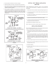
When multiple units are direct vented through a wall (3" or 4" venting), no
intake air terminal should be lower than the highest exhaust vent terminal.
NOTE: This water heater can only be vented with PVC pipe certied and
marked as complying with ULC S636 and glued with IPEX System 636
CPVC Cement Product .