


This Manual is Designed to Make it as Easy as Possible for You
to Assemble, Install, Operate, and Maintain Your Ceiling Fan
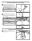
Unpacking Instructions
For your convenience, check-off each step. As each step is completed, place a check mark. This will ensure that all
steps have been completed and will be helpful in finding your place should you be interrupted.
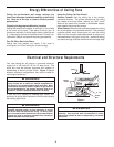
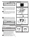
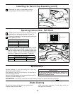
Wiring outlet box and box connectors must be of type
required by local code. The minimum wire would be a 3-
conductor (2-wire with ground) of the following size:
NOTE: Place the parts from the loose parts bags in a small
container to keep them from being lost. If any parts are missing,
contact your local retailer.
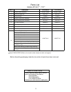
Tools Needed for Assembly Materials
Wire Size A.W.G.Installed Wire Length
14
12
Up to 50 ft.
50 - 100 ft.
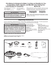
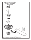
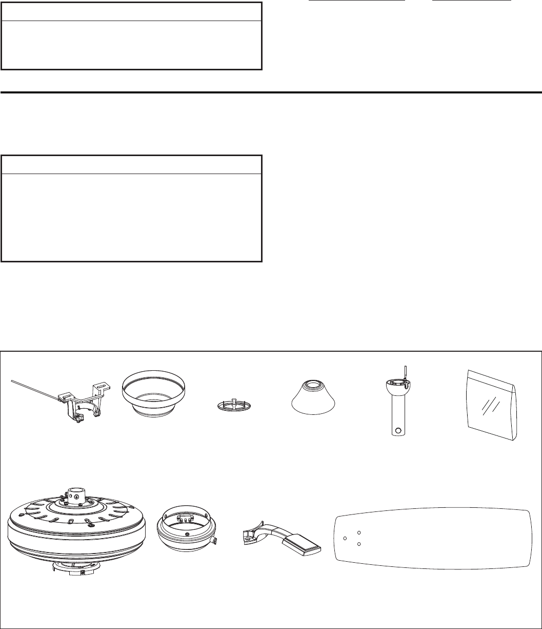
NOTE: If you are uncertain of part description, refer to
exploded view illustration. (Figure 1, page 11)
3
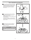
1. Check to see that you have received the following
parts:
Blade Holder Set
Hardware Bag
Fan Motor
Assembly
Downrod/
Hanger Ball
Assembly
Ceiling Canopy
• One Phillips head screwdriver
• One stepladder
• One ¼” blade screwdriver
• One wire stripper
• Four wire connectors
(supplied)
▲
WARNING
Do not install or use fan if any part is damaged or
missing. This product is designed to use only those
parts supplied with this product and/or any accessories
designated specifically for use with this product by
Fanimation. Substitution of parts or accessories not
designated for use with this product by Fanimation could
result in personal injury or property damage. Contact
your retail store for missing or damaged parts.
▲
WARNING
Before assembling your ceiling fan, refer to section on
proper method of wiring your fan (page 4). If you feel you
do not have enough wiring knowledge or experience,
have your fan installed by a licensed electrician.
• Fan Motor Assembly
• Switch Cup Assembly
• Hanger Bracket Assembly
• Downrod/Hanger Ball
Assembly
• Ceiling Canopy
• Canopy Screw Cover Assembly
• Motor Coupling Cover Assembly
• Blade Holder Set
• Blade Set
• Hardware bag:
– Eleven ¼-20 x 14mm
(blade holder to fan motor hub)
phillips screws with lockwashers
– Sixteen
3
/16-24 x 7.5mm
fiber washers (blade to blade holder)
washer-head screws with
– Four wire connectors
– Chain Coupler
– Chain Fob
– Balance Kit
Hanger Bracket
Assembly
Blade Set
Switch Cup
Assembly
Canopy
Screw Cover Assembly
Motor
Coupling Cover
Assembly