


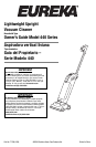
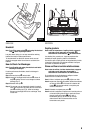

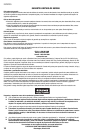

FIG. 1
5
ENGLISH
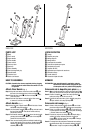
PARTS LIST
●
A
Body
●
B
Floor nozzle
●
C Upper
handle
●
D
Lower handle
●
E
Power switch
●
F
Dust cup latch
●
G
Dust cup
●
H
Filter assembly
●
I
Stair cleaning hand grip
●
J
Handle button
●
K
Electrical cord
●
L
Quick cord release
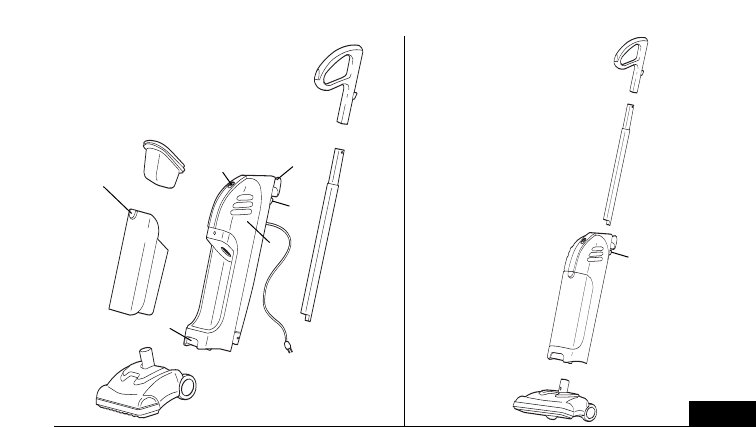
HOW TO ASSEMBLE
CAUTION: Assemble the cleaner completely before plugging
into an electrical outlet. Make sure switch is in the
Off position.
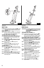
Attach Floor Nozzle (Fig. 1)
Step 1: Align the lock button on the floor nozzle neck
●
B
with
the hole in the receiving tube on the main body
●
A
.
Step 2: Slide the floor nozzle
●
B
into the main body
●
A until it
clicks into place
.
Step 3: Push the lock button in and pull on the floor nozzle
●
B
to remove it from the main body
●
A
.
Attach Handle (Fig. 1)
Step 1: Align flat side of upper handle
●
C
with flat side of lower
handle
●
D
and press together.
Step 2: Line the handle assembly
●
C
and
●
D
up with the hole in
the top of the bod
y
●
A
.
Fla
t side of handle and loop
should face forward.
Step 3: Push handle assembly
●
C
and
●
D down into body while
pressing the handle button
●
J
on back of the bod
y
●
A
.
Handle will c
lick into place.
Step 4: There are two handle positions a
vailable:
Handle all the
way up and handle all the way down. Handle button
●
J
needs to be depressed to raise and lower the handle
assembly
●
C
and
●
D
.
ESPAÑOL
LISTA DE PARTES
●
A
Cuerpo
●
B
Boquilla para pisos
●
C Mango superior
●
D
Mango inferior
●
E
Interruptor de encendido
●
F
Traba del recipiente para polvo
●
G
Recipiente para polvo
●
H
Conjunto de filtro
●
I
Agarradera para limpieza de escaleras
●
J
Botón del mango
●
K
Cordón eléctrico
●
L
Liberación rápida del cable
ARMADO
PRECAUCIÓN: Arme completamente la aspiradora antes de
enchufarla al tomacorriente.Asegúrese de que
el interruptor esté en la posición Off (Apagada).
Colocación de la boquilla para pisos (Fig. 1)
Paso 1
:
Alinee el botón de traba del cuello de la boquilla para pisos
●
B
con el orificio del tubo receptor del cuerpo principal
●
A
.
Paso 2: Deslice la boquilla
●
B
dentro del cuerpo principal
●
A
hasta que encaje en su sitio con un clic.
Paso 3: Presione el botón de traba y jale la boquilla para pisos
●
B
para retirarla del cuerpo principal
●
A
.
Colocación del mango (Fig. 1)
Paso 1: Alinee el lado plano del mango superior
●
C
con el lado
plano del mango inferior
●
D
y presione para conectarlos.
Paso 2: Alinee el conjunto de mango
●
C
y
●
D
con el orificio de
la parte superior del cuerpo
●
A
. El lado plano del mango
y el bucle deben mirar hacia adelante.
P
aso 3:
Presione el conjunto de mango
●
C
y
●
D
hacia abajo y
adentro del cuerpo mientras presiona el botón del
mango
●
J
de la parte trasera del cuerpo
●
A
.
El mango
calzará en su sitio con un clic.
Paso 4: El mango tiene dos posiciones:Totalmente hacia arriba y
totalmente hacia abajo. Es necesario presionar el botón
●
J
para subir o bajar el conjunto de mango
●
C
y
●
D
.
●
H
●
F
●
G
●
I
●
B
●
B
●
A
●
A
●
C
●
C
●
D
●
K
●
D
●
E
●
J
●
J
●
L