


9
This unit is pre-wired to work with external control sys-
tems, heat-on-demand options and other external time
clock overrides. Refer to the external control system’s
instructions, and page 22 of this manual, for installa-
tion information.
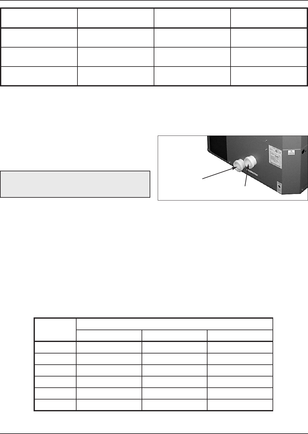
Water Connections
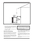
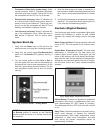
1. Connect the heat pump pool heater in the return
water line between the filter and the pool/spa. See
the Plumbing Diagrams beginning on page 16.
2. Connect the filter outlet to the fitting marked
WATER IN at the bottom front of the unit.
3. Connect the fitting marked WATER OUT to the
return piping to the pool/spa. Unit inlet/outlet con-
nection fittings are 2-inch PVC unions.
Water connections from the unit to the main return
line can be PVC pipe or flexible pipe approved for
the purpose and, in either case, should be at least
equal in size to the main pool/spa circulation pip-
ing.
4. In cold weather (freeze zone) areas, shutoff valves
(ball or gate type) must be installed at the unit inlet
and outlet to facilitate service and cold weather
drain-down.
5. Operate the pump and check the system for leaks.
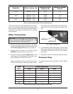
Pressure Drop
For system pressure drop information, refer to Table B
below.
CAUTION: The heat pump pool heater inlet and
outlet connections are NOT interchangeable. They
must be connected as instructed below.
Fig. 2: Water Connections
WATER IN
WATER OUT
Table B: Pressure Drop Across Heat Pump Pool Heater
Flow
(gpm)
Pressure Drop (psi)
5310 6310 8320
10 1 1 1
20 2 3 3
30 4 6 9
40 7 9 9
50 10 10 10
60 11 11 11
Model No. VAC in - Phase - Hz
Minimum Circuit
Ampacity (A)
Maximum Breaker
Size (A)
5310 208/230 - 1 - 60 38.2 50
6310
208/230 - 1 - 60
208/230 - 3 - 60
33.45
25.45
60
50
8320
208/230 - 1 - 60
208/230 - 3 - 60
37.45
33.3
60
60
Table A: Typical System Electrical Power Requirements