


2
110499
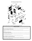
Cooler Installation
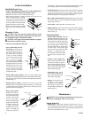
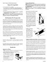
Installing House Legs
• NOTE: If installing unit without the use of the installation kit,
omit these directions and those pertaining to Fig. 2.
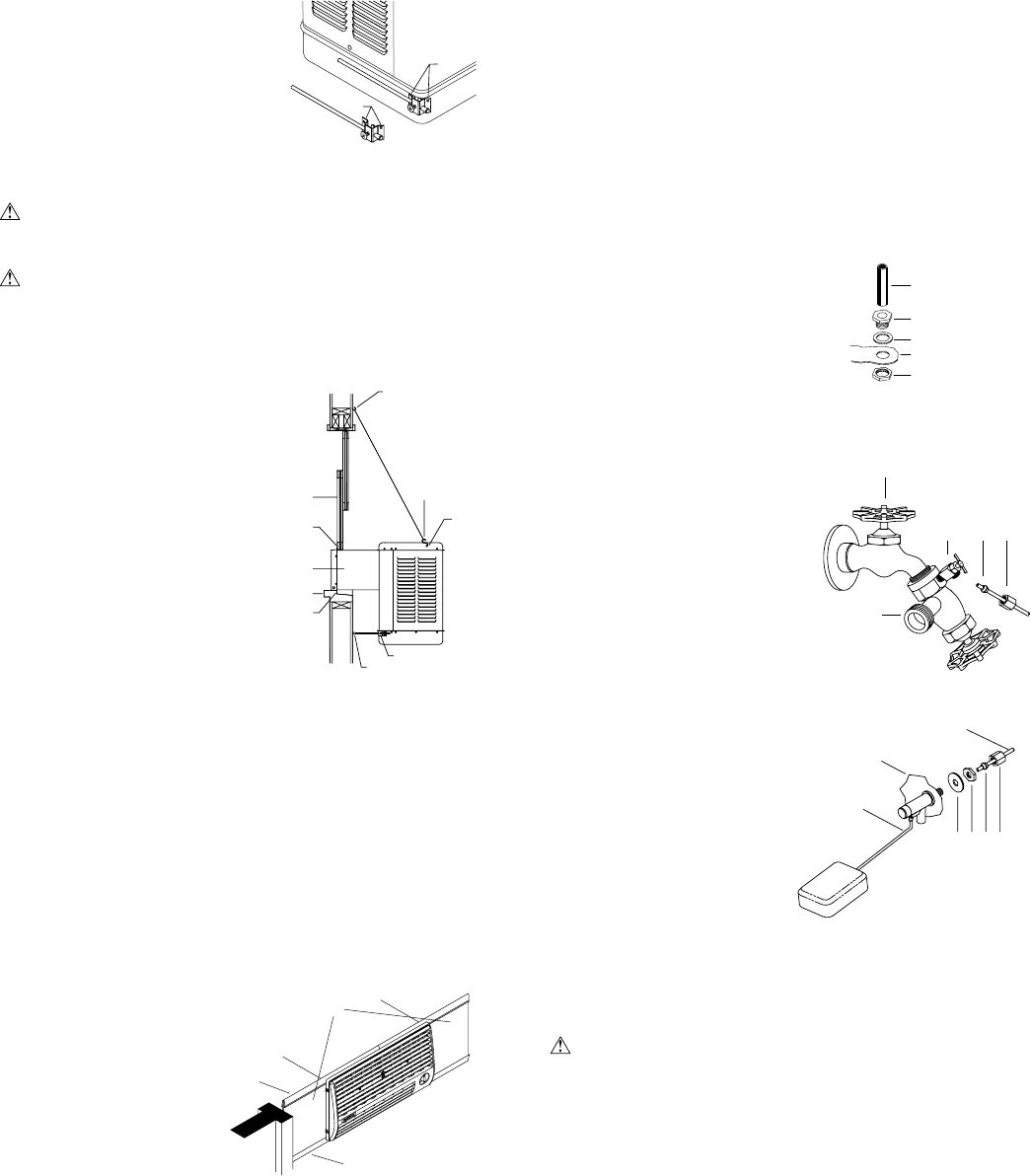
• Remove two corner screws in bottom pan (A-Fig. 1).
• Place house leg bracket at corner of bottom pan, using two top
holes in bracket (B-Fig. 1). Replace
the two previously removed screws to
hold house leg bracket in place (As
shown by dotted house leg bracket).
• Mount other side in same manner.
• Refer to the instructions “Adjust
house legs” below for adjusting house
leg .
Mounting Cooler
CAUTION: Make sure that the mounting surface is strong
enough to support the operating weight of the cooler when in use.
(For operating weight, see Specifi ca tion Table.)
CAUTION: Never plug in cooler until installation is complete
and unit has been tested for rigidity.
• Lift out all removable louvered sides.
• Screw chain hooks into win-
dow facing. Position the two
chain hooks above the neck of
the cooler a distance equal to
the width of the cooler apart
(A-Fig. 2). Hook one hanger
chain in each hook and then
one “S” hook in the other
end of each chain. NOTE:
Chain hooks supplied with this
mounting kit have wood screw
threads for wood walls. Con-
crete, brick walls or concrete
blocks require sufficiently
strong wing nuts or anchors
with mating hooks.
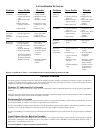
• Install window panel retainers. Place two panel retainer strips
onto bottom of neck fl ange and position to the width of the window.
Cut the strips to fi t if necessary. These strips hold the window fi ll-
in panels (Fig. 3).
• Position cooler in window. Position neck of cooler so that the
fl ange (E-Fig. 2) is snug against edge of sill (H-Fig. 2). With cooler
in position, hook the “S” hooks into the holes of the top pan near
the back of the cooler (B-Fig. 2).
• Break fill-in panels
to fi t. With cooler in-
stalled, as described
above, measure for each
window fill-in panel
and score with sharp
knife and straight edge
guide to desired width.
To break window fi ll-
in panels, the panel
should be laid over the
edge of a straight fl at
surface at the point to
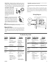
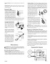
Connecting Water
• Install overfl ow assembly. Place the
nipple through the hole in the pan, with
the rubber washer between the pan
and the head of the drain nipple (Fig.
4). Screw the nut onto the nipple and
draw up tight against bottom of pan.
Insert the overfl ow pipe in the nipple
to retain water. The overfl ow pipe
may be removed to drain pan when
necessary. A garden hose may
be screwed onto the drain nipple
to drain water away from your
unit.
• Connect water supply line.
Install a sillcock and water valve
on a faucet as shown by fi gure 5.
Run 1/4 inch tubing from sillcock
valve to cooler. Place the nut and
ferrule on the tubing and tighten
the nut until water tight.
• Install fl oat valve. Install
valve in the provided hole in
the louvered side (Fig. 6) and
attach water supply line.
• Fill pan. Allow water to fi ll
to within 1” of top of pan
and ad just fl oat to maintain
this water level. This can be
accomplished by bending the
fl oat rod (Fig. 6).
be broken off. Apply pressure on the edge of the panel that extends
over the edge of the surface and break off unwanted piece.
• Install fi ll-in panels. Place one window fi ll-in panel on each side
of grill and into panel retainer strip at bottom of grill. Place the
other panel retainer strips onto top of neck fl ange and fi ll-in panels.
Be sure the panels are snug up against cooler neck.
• Place window behind retainer strip. Raise back of cooler so that
the window (D-Fig. 2) may be brought down behind top of panel
retainer strip (C-Fig. 2).
• Level Cooler. Adjust the chains to level the cooler.
• Adjust house legs. Pull out house legs so that the rubber bumpers
rest against house siding (F-Fig. 2). Tighten screw in retaining
collar. (G-Fig. 2).
Maintenance
WARNING: Before doing any maintenance be sure power is
off and unit is unplugged. This is for your safety.
Spring Start-Up
• Change Pads. Aspen pads should be replaced once or twice a
season, depending upon the length of the season. At the beginning
and at mid season a clean pad is more absorbent and effi cient and
will deliver substantially more cool air.
Float Rod
Water Supply
Line
Washer
Nut
Ferrule
Nut
Fig. 6
Louvered Side
Faucet
Water Supply
Valve
Sillcock
Ferrule
Nut
Fig. 5
Rubber Washer
Overfl ow Pipe
Nipple
Bottom Pan
Nut
Fig. 4
D
A
B
C
E
F
G
H
Window
Neck
“S” Hook
Fig. 2
Fig. 1
B
A
Window Fill-In
Panels
Top Panel
Retainer
Bottom Panel
Retainer
Fig. 3