


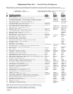

2
110522-1
Cooler Installation
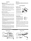
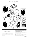
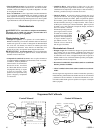
Installing Casters
Note: The installation kit
includes (2) swivel cast-
ers with brake, (2) swivel
casters without brake, (16)
tinnerman nuts and (16)
1/4-20 x 1/2 screws.
• Place the unit on its side.
Place the tinnerman nuts on
the caster bracket on the bot-
tom pan as shown in fi gure
1.
• Attach the casters to the
brackets with the screws provided.
Operation
Manual Control Units
• Pump setting. The rotary switch has 6 settings. The “Pump”
setting will operate the pump without the blower. For best results
turn the switch to “Pump” for a few minutes to wet the pads before
operating the fan.
• High and low cool settings. The “High Cool” and “Low Cool” set-
tings operate both the pump and the blower. Turn the unit to “Low
Cool” when possible. This lower speed allows the air to stay longer
in the wet pads and therefore increases it’s cooling effi ciency.
• High and low vent settings. The “High Vent” and “Low Vent”
settings operate the blower without the pump. This is useful on
cool nights or at times when just a fan is desired.
Remote Control Units
These units may be controlled using the 3 buttons on the front panel
of the cooler or with the remote control.
• PUMP button. Pressing this button toggles the pump on and off.
When the LED is lit, the pump is running. For best results turn
on the pump for a few minutes to wet the pads before operating
the fan. The pump must be on while operating the fan for cooling.
You may also want the pump turned off at times when just a fan is
desired.
• FAN button. Pressing this button will cycle the fan through High
Speed / Low Speed / Off. The LED’s on the front of the control
indicate wether the fan is on high speed, low speed or off (no LED’s
lit). Note: There will be a 2 second delay between a button press
and the operation of the fan.
• ON/OFF button. Pressing this button while the pump or fan is on
will turn everything off. Pressing it again while in the off state will
return the fan and pump to their previous operating settings. When
fi rst plugging in the cooler or after power has been interrupted,
pressing the On/Off button will start the cooler in the default state
which is with the pump on and the fan on high.
• Remote Control. To operate the cooler with the remote you must
be within 20 feet and in sight of the cooler. Aim the remote at the
front panel. The buttons on the remote control have the same func-
tions as the buttons on the front panel of the cooler. The remote
uses two AAA alkaline batteries which are included. A holder for
mounting on a wall is also included with the unit.
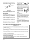
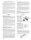
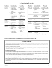
Connecting Water
• Install drain assembly. Place the
nipple through the hole in the pan,
with the rubber washer between the
pan and the head of the drain nipple
(Fig. 2). Thread nut onto nipple and
draw up tight against bottom of pan.
Thread the drain cap to the nipple and
tighten water tight.
• Install fl oat valve. Refer to fi gure 3. Install the valve in the pro-
vided hole in the corner post ((R)M301A, (R)M401A) or louvered
side (M201A) using the provided washer and nut. Install the
included garden hose adapter to the fl oat as shown if attaching a
garden hose to the unit. A 1/4 inch water line may also be used to
supply a continuous amount of water to the unit.
• Fill pan with water. You may fi ll the pan manually for up to 3
hours of cooling. For automatic fi lling you may attach a garden
hose to the garden hose adapter or a 1/4 inch water line to the fl oat
valve.
Fig. 1
Bottom Pan
Nipple
Rubber Washer
Nut
Drain Cap
Fig. 2
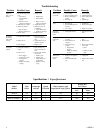
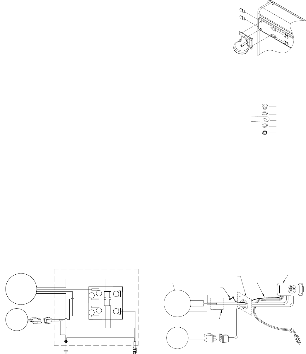
Wiring Diagrams
White-Com.
Black-Hi
Black
Blower
Motor
Pump
Motor
Red-Lo
White-Com.
Green-Ground
Green
Switch
A
B
1
2
3
4
Ribbed-Com.
Plain
Green
Exhaust Air
If the unit is used in an enclosed area, open windows or doors to
ensure adequate exhaust. Without an outlet to exhaust the air,
humidity will build up in the enclosed space and the unit will not
cool adequately.
Manual Control Remote Control
Hi
Low
Gnd
Com.
Black
Red
Green
White
Ground
Wire
Blower Motor
Pump
Motor
Blower Panel
Control
Ground
Screw
Junction Box
(RM301A)