


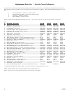

4
110525
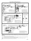
Typical Electrical Wiring Diagrams
WARNING: Electrical hookup should be performed by a qualifi ed electrician. All electrical wiring must conform to national and
local standards.
NOTE 1. All switches, motor starters, transformers, fuses, junction boxes, receptacles, receptacle boxes, cover plates, and conductors shall be supplied by the
installer and must comply with local and national electrical codes.
NOTE 2. The national electric code requires a disconnect switch located at equipment if the main disconnect at equipment controller is not visible from the equip-
ment. If more than one disconnect is used they must be mounted adjacent to one another.
NOTE 3. A receptacle for a NEMA 5-15P plug is required for 120V recirculating pump and a receptacle for a NEMA 6-15P plug for 230V pump.
NOTE 4. The control contacts may be part of a switch, thermostat or other control device.
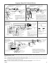
• Three phase single speed blower motor
• Three pole motor starter with overload
protection
• 120V single phase control and pump shown.
If 240V control and pump are to be used, then
both legs of power supply must be fused.
Main Disconnects
See Note 1
Control Contacts
See Note 4
Disconnect Switch At Cooler
See Note 1&2
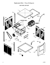
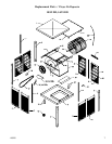
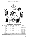
Cooler Cabinet
See Note 3
Pump Motor
Equipment
Ground
Blower Motor
Motor Starter With
Overload Protection Sized
To Match Motor Full Load
Current
See Note 1
L2
L1
H
P
T1
T2
T3
Disconnect Switch At
Cooler
See Notes 1 & 2
Gnd
208, 240, or 480V
3 Phase
Power Supply
120V
1 Phase
Power Supply
Fuses
See Note 1
Gnd
L3
L1
N
Gnd
208, 240, or 480 Volt, 3 Phase Blower & 120 Volt 1 Phase Pump & Control Electric Supply
N
Gnd
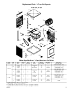
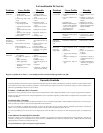
Motor Starter With
Overload Protection
Sized To Match Motor
Full Load Current
See Note 1
Fuses
See Note 1
Main Disconnect
See Note 1
Disconnect Switch At Cooler
See Notes 1 & 2
Disconnect Switch At Cooler
See Notes 1 & 2
Pump Motor
Blower Motor
Equipment
Ground
T1
T2
T3
Cooler Cabinet
See Note 3
L2
Transformer
See Note 1
208, 240 or 480V
3 Phase
Power Supply
H
P
• Three phase single speed blower motor.
• Three pole motor starter with overload protection.
• 120V single phase pump powered by a transformer.
Transformer may be omitted when 240V control &
pump are used with a 240V supply.
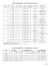
Typical Control Contacts
Function and Connection
L - Low Fan
P - Pump
H - Hi Fan
L1 - Supply Power
Function Connection
Off None
Pump Only L1-P
Hi-Cool L1-H
* Low-Cool L1-L & L1-P
Hi-Fan L1-H
* Low-Fan L1-L
* Omit for single speed blower motor
• 115 Volt single phase blower motor.
• 120 Volt pump motor.
• Diagram shown for two speed motor.
Low speed circuit drawn with dashed
lines is not required for single speed.
Equipment
Ground
Pump Motor
Blower Motor
Cooler Cabinet
Fuses
See Note 1
Main Disconnect
See Note 1
120 Volts
1 Phase
Power Supply
N
H
Disconnect Switch At Cooler
See Notes 1 & 2
L1
N
See Note 3
L
GndGnd
120 Volt, 1 Phase Electric Supply
Control Contacts
See Note 4
P
• 230 Volt single phase blower motor.
• 120V pump motor shown. Trans-
former may be omitted when a 240V
pump is used with a 240V supply
• Diagram shown for two speed motor.
Low speed circuit drawn with dashed
lines is not required for single speed.
Equipment
Ground
Pump Motor
Blower Motor
Cooler Cabinet
See Note 3
Transformer
Fuses
See Note 1
208 or 240V
1 Phase
Power Supply
L2
H
P
Control Contacts
See Note 1
Disconnect Switch At Cooler
See Notes 1 & 2
Gnd
L
240 Volt, 1 Phase Electric Supply
Main Disconnect
See Note 1
L1
L2
Gnd
120V
Gnd
Gnd
L3
L1
120
V
Control Contacts
See Note 4
208, 240, or 480 Volt, 3 Phase Blower Electric Supply With Transformer For Pump & Control