


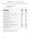
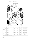
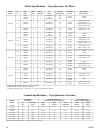

2
110525
Operation
For the best cooling performance, if the pads are dry, pre-wet the pads
by running the pump for a few minutes before starting the blower.
These coolers may also be used without water for ventilation purposes.
When outside air is cool (for example, at night) or when humidity is
high the water pump can be turned off.
IMPORTANT: To cool effi ciently, you must exhaust the stale or used
air from the building. Open windows or doors or use exhaust fans
located away from the cooler and in the direction you wish to cool
the air. The air will fl ow in the direction of the exhaust openings. A
common guide for the amount of exhaust opening needed is to have
at least 2 square feet of opening per 1000 CFM.
Safety Rules
1. Read instructions carefully.
2. Disconnect all electrical service that will be used for the unit before
you begin the installation.
3. Electrical hook up should be done by a qualifi ed electrician, so
that all electrical wiring will conform to your local standards.
4. For a maximum safety precaution, make sure cooler cabinet is
properly grounded to a suitable ground connection.
5. Cooler must be connected to proper line current, voltage and cycle,
as stamped on cooler motor and pump motor specifi cation plate.
6. Do no allow pump to tip over and become submerged.
7. Always DISCONNECT POWER before installing unit or
performing any maintenance.
Installation
CAUTION: Make sure that the mounting surface is strong
enough to support the operating weight of the cooler when in use.
(For operating weight, see Specifi cation Table.)
CAUTION: Never plug in cooler until installation is complete
and unit has been tested for rigidity.
CAUTION: Make sure all bolts are securely tightened before
starting the cooler.
• Ductwork. See the General Specifi cation table for the duct open-
ing dimension for your specifi c cooler. For down discharge units
models 10/12DD and 14/21DD, the duct must go inside the opening.
Size these ducts slightly smaller than the duct opening in the cooler.
On 75/85DD and 95DD models the duct may go to the inside or
outside of the duct fl ange. The side discharge units have a 1 inch
fl ange. Size these ducts larger than the duct opening to fi t over the
fl ange of these units.
Note: Curbs are not provided. The installer is responsible for
providing curbs or other means to support the cooler.
Water Connection
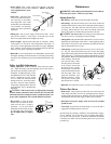
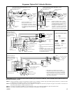
• Overfl ow assembly. Remove nut and place nipple through the hole
in the pan, with the rubber washer between the pan and the head
of the drain nipple (Fig. 3). Screw on
nut and draw up tight against bottom
of pan. Insert overfl ow pipe in nipple
to retain water. Overfl ow pipe may be
removed to drain pan when necessary.
A garden hose may be screwed on the
drain nipple to drain water away from
your unit.
• Pump. The pump must be secured to prevent it from tipping over.
Secure the pump to the pump mounting bracket. For the 10/12 and
14/21 models, remove the mounting screw on the top of the pump
and using this same screw, secure the pump to the pump mount. To
secure the pump for the 75/85 and 95 models, slide the pump into
the slot of the pump mount and secure with the plastic retainer.
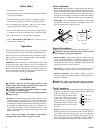
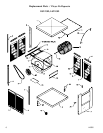
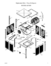
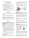
Motor Installation
• Mount motor. Slide the heads of the provided carriage bolts into
the slots of the adjustable channels. Slide these channels sideways
in the slotted holes to align with the holes in the motor base and to
align the motor shaft with the blower pulley. Mount the motor to
the motor mount using these carriage bolts and the washers and nuts
provided (see Fig. 1). Make sure all bolts are securely tightened.
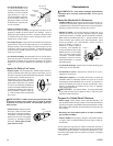
• Install pulley. Install the adjustable motor pulley so that it aligns
with the blower drive pulley (see Fig. 2) and tighten set screw. See
page 3 for instructions on adjusting pulley.
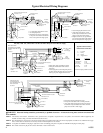
Electrical Installation
NOTE: Local building code regulations must be observed.
WARNING: Disconnect all electrical service that will be used
for this unit before you begin the installation.
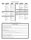
• Electrical Supply. Cooler must be supplied with the proper line
current, voltage and frequency, as stamped on cooler motor and
pump motor specifi cation plate. See the wiring diagrams on page
4 for typical electrical connections. NOTE: Connecting improper
voltage to motor will void motor warranty.
• Wire sizing. The conductor sizes are to be determined by motor
loads and length of run per national and local electrical codes.
• Switches or contactors. Motors require switches or contactors
of proper current capacity and should be sized and installed by a
competent electrician.
WARNING: Make sure that cooler cabinet is properly
grounded to a suitable ground connection for maximum safety.
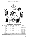
Fig. 1
Adjustable
Channels
Blower
Housing
Motor
Pulley
Blower
Pulley
Fig. 2
Rubber Washer
Overfl ow Pipe
Nipple
Bottom Pan
Nut
Fig. 3