


29
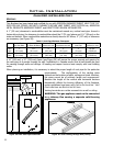
Initial Installation
QUALIFIED INSTALLERS ONLY
eLectRicaL RequiRements:
The replace must be electrically connected and grounded in accordance with local codes or, in the
absence of local codes, with the current CSA C22.1 CANADIAN ELECTRICAL CODE Part 1, SAFETY
STANDARDS FOR ELECTRICAL INSTALLATIONS, OR THE NATIONAL ELECTRICAL CODE ANSI / NFPA 70
in the US.
WARNING: The electrical grounding instructions must be followed. This appliance is equipped with a
three-prong (grounding) plug for your protection against shock hazard, and should be plugged directly
into a properly grounded three-prong outlet. DO NOT cut or remove the grounding prong from this
plug.
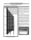
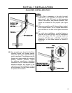
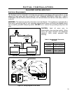
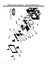
Figure 40. Wiring Diagram For Fan Control.
CAUTION: Label all wires prior to
disconnection when servicing controls. Wiring
errors can cause improper and dangerous
operation. Verify proper operation after
servicing.
Fan Control
Black Black
Black
Short
Black
Long Black
White
White
Green/Yellow
Electrical
Power Cord
Green
120°F (49°C)
Temperature Sensor
Fan
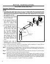
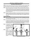
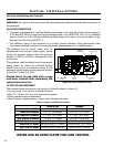
Figure 41. Wiring Diagram For Gas Valve.
COOL / HEAT
PROGRAM
DOWN
UP
70 ° F
70 ° F
O
N
OFF
Optional
Remote
Control
ON/OFF/Remote
Thermostat Switch
Purple
Thermocouple
Blue
Thermopile
Grey
Inlet
Pressure
Tap
Gas Control
Valve
Manifold
Pressure Tap
Pilot Adjustment
Screw
Optional
Wall Switch
Optional
Thermostat
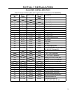
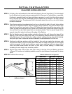
Wire Size Max. Length
14 gauge 100 ft (30.48 m)
16 gauge 60 ft (18.29 m)
18 gauge 40 ft (12.00 m)
20 gauge 25 ft (7.62 m)
22 gauge 18 ft (5.49 m)
Table 8. Recommended Thermostat
Wire Size.