


V
e
n
t
R
e
s
t
r
i
c
t
o
r
P
o
s
i
t
i
o
n
s
5
4
3
2
1
0’
(0m)
0’
(0m)
5’
(1.52m)
5’
(1.52m)
10’
(3.05m)
10’
(3.05m)
15’
(4.57m)
15’
(4.57m)
20’
(6.10m)
25’
(7.62m)
30’
(9.14m)
18’
(5.49m)
Initial Installation
QUALIFIED INSTALLERS ONLY
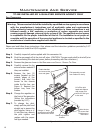
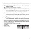
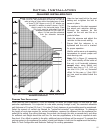
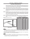
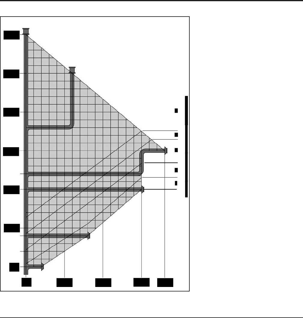
Figure 12. Possible Vent Congurations for Top Vented; Vertical and
Horizontal Terminations.
NOTE: The total length of the vent pipes can not exceed 30
feet (9.14 m). Any combination of rise and run can be
used as long as it lays within the shaded area (a total
of three (3) 90° elbows or six (6) 45° elbows can
be used). In addition to what is shown, if a 90°
elbow is used in the horizontal plane, 3 feet
(91.4 cm) must be subtracted from the
allowable horizontal run (for each 45°
elbow, 1 feet must be subtracted
from the allowable horizontal
run).
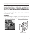
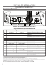
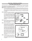
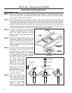
Slide the hex head bolt to the next
setting and re-tighten the bolt to
secure in place.
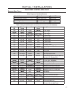
The numbers in this chart represent
the actual vent restrictor settings.
Although the numbers do not
appear on the unit use this as a
guide to follow.
Undo the setscrew and adjust the
restrictor to the correct setting.
Ensure that the setscrew is re
tightened and the unit is checked
for proper operation.
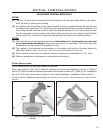
Wait for unit to warm up to operating
temperature to ensure proper and
clean burning unit.
Note: 0,0 in Figure 12 represents
a 90˚ bend directly off the outlet of
the unit, in all horizontal instances
except when using Selkirk and
having less than a 4 ft (1.22 m)
rise and 8 ft (2.44 m) horizontal
offset. In this case, a 1 foot (30.5
cm) rise must be added below the
90˚ bend.
15
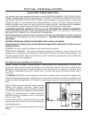
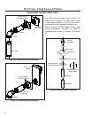
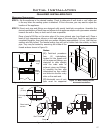
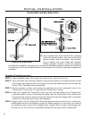
PLANNING YOUR INSTALLATION:
When planning your installation, it will be necessary to select the proper length of vent pipe for your
particular requirements. It is important to note when passing through a wall, the maximum allowable
wall thickness is 10 inches (25.4 cm), 1 inches (3.8 cm) clearance to combustibles must be maintained.
Select the amount of vertical rise desired for “vertical-to-horizontal” type installations. To determine
the length of vent pipe required for vertical installations, measure the distance from the appliance ue
outlet to the ceiling, the ceiling thickness, the vertical rise through the attic or second story, and allow
for sufcient vent height above the roof line. For two story applications, a re stop is required at each
oor level. If an offset is needed in the attic, additional pipe and elbows will be required. To connect the
venting system to the appliance ue outlet, a twist-lock adapter is built into the appliance at the factory.
Refer to ‘Vent Conguration and Restrictor Settings’ for venting parameters.