


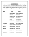

Type B-1 Vent Pipe is designed for installation within a building -- it is not intended for outside
use unless it is enclosed in a protective structure and insulated. The requirement for this is clearly
stated in the Venting Tables, Category 1 – Central Furnaces, AGA and GAMA “current edition” for
U.S. Installations and Standards for Gas Vents; National Standards of Canada and CAN/CGA-
B149.1-M91 for installations in Canada “current edition”. Condensation of exhaust gases may
occur and liquid may run down your chimney if the pipe is not enclosed and insulated. The flue
blockage sensor will also shut the unit down if the stove is not exhausting properly.
B. Existing Flue System
This stove may be connected to an existing pre-fabricated chimney or masonry chimney as
long as the B-1 Vent Pipe passes through the entire length of the chimney. In cases where it is
not possible to use rigid pipe, the four-inch (4”) flex pipe can be substituted. A qualified service
person is best suited for properly retrofitting your existing flue system for use with a gas product.
This vented gas fireplace heater must not be connected to a chimney serving a
separate solid fuel-burning appliance.
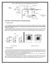
SECTION II: UNIT PREPARATION AND PRE-INSTALLATION
A. Unit Preparation
Note: We recommend using a handcart when unloading and placing this stove.
Never attempt to handle this unit without help.
When your unit arrives, it should first be uncrated. Remove all packing material outside the
stove and from the interior of the firebox, and open the firebox by unscrewing the bolt on the right
side of the doorframe. Remove the inflated air bag, instruction manual and wall thermostat from
the interior of the stove. Note: Do not remove the ceramic logs. If you do so by mistake, follow
the guidelines below for proper placement of the logs.
B. Log Placement
The logs are in the proper position when the unit leaves the plant. However, during the
shipping of the unit the assembly can become misarranged. Check to be sure the logs are still
located in the provided slot behind the front portion of the burner tube and the rear of the
assembly is touching the firewall. The front log should be straight up or perpendicular to the floor.
Contact the factory at 1-800-245-6489 if you see a cracked or broken log.
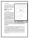
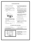
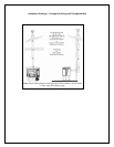
C. Top or Rear Vent
Your stove comes with the option of venting out of the
top or rear of the unit. The stove must
be set up for the desired venting direction prior to operating the unit.
First, remove the two screws that hold the grilled top onto the stove. They are located on the
back of the stove near the top.
For the top exit installation, place the flue collar on the top of the stove and fasten it with the
four (4) bolts, nuts and washers. Install the flue cover plate on the rear opening of the unit using
the supplied bolts, nuts and washers.
Next,
find the vent safety shut-off switch inside the draft hood on the back of the stove. It is the
small disc-shaped object screwed to an L-shaped bracket; there are two (2) sets of holes on this
bracket.
Position this vent safety shut-off switch as far up in the flue as possible, or in a direction
heading toward the ceiling
. This is accomplished when the lower set of holes in the bracket is
aligned with the two holes in the back of the stove.
For the rear exit method, place the flue collar on the rear of the stove and fasten it with the
four (4) bolts, nuts and washers. Install the flue cover plate on the top of the unit with the supplied
bolts, nuts and washers.