


WARNING: IF THE AREA IN WHICH THE HEATER MAY BE OPERATED IS
SMALLER THAN THAT DEFINED AS AN UNCONFINED SPACE, PROVIDE
ADEQUATE COMBUSTION AND VENTILATION AIR BY ONE OF THE METHODS
DESCRIBED IN THE NATIONAL FUEL GAS CODE, ANSI Z223.1 (SECTION 5.3).
“The National Fuel Gas Code defines a confined space as a space whose volume is less than
50 cubic feet per 1,000 BTU per hour (4.8 m3 per KW) of the aggregate input rating of all
appliances installed in that space and an unconfined space as a space whose volume is not less
than 50 cubic feet per 1,000 BTU per hour (4.8 m3 per KW) of the aggregate input rating of all
appliances installed in that space. Rooms communicating directly with the space in which the
appliances are installed, through openings not furnished with doors, are considered a part of the
unconfined space.” For example, add the BTU for each gas appliance in the room and then
compare the size of the room to see if it will accept 1,000 BTU for each 50 cubic feet. The cubic
feet in the room can be calculated by multiplying the length by the width times the height of the
ceiling. If the room has 8-foot ceilings and is 11 feet by 15 feet, it would have 1,320 cubic feet
(8x11x15). You can now multiply by 1,000 and divide this cubic volume by 50 cubic feet/1,000
BTU and the result (1,320x1,000÷50) of 26,400 represents the accumulated BTU capacity for
this room size. If the result is greater than the accumulated BTU of all the appliances in the room,
then the room is an unconfined space and qualifies for installation of the unvented heater. If the
result is less than the accumulated BTU of all appliances in the room, then the room is a confined
space and the unvented heater should not be installed in this room.
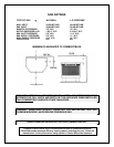
The formula for this calculation: BTU/HT = L x W x H x 1,000
50
If the room has a door to an adjoining room, use only the dimensions to the room where the
heater will be located. If the room has an open area between two rooms the total length, width
and height can be used in your calculations.
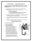
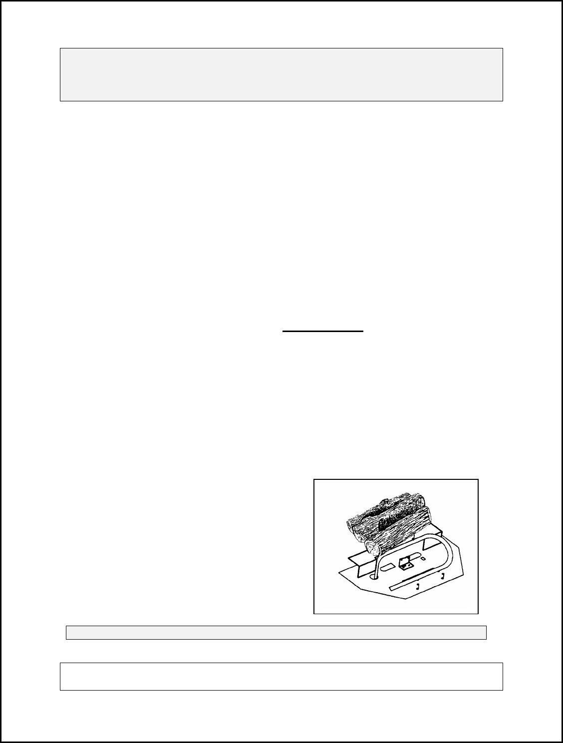
LOG ASSEMBLY
IMPORTANT! The logs MUST be placed exactly as shown in the diagram. If there is any
evidence of carbon or blackening on the logs they may be incorrectly placed in the unit.
NOTE (Models manufactured prior to 3/00) – For removal of the screen you must:
1) Lift up on the screen.
2) Push the screen toward the logs,
past the clips.
3) Push the screen down to the bottom
of the firebox.
4) Pull the top of the screen forward
and up.
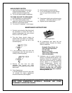
For models manufactured 3/00 and later, simply
remove the four Phillips Head screws to take out
the screen. Do not over-tighten the screws when
reinstalling.
WARNING: ANY CHANGE TO THIS HEATER OR ITS CONTROLS CAN BE DANGEROUS.
MODIFICATIONS TO THIS APPLIANCE MAY CAUSE SERIOUS INJURY OR DEATH.
ANY CHANGES WILL VOID THE WARRANTY.