


6
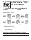
Installation Instructions and Owner’s Manual
Unvented Natural Gas Fired Room Heater
Figure 4
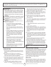
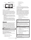
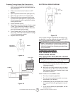
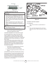
FASTENING HEATER TO WALL
Mounting Bracket
The mounting bracket in located on the back panel of
heater (see gure 5). It has been taped there for ship-
ping. Remove mounting bracket from back panel.
Figure 5
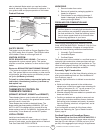
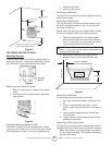
Removing Front Panel of Heater
1. Remove three screws on bottom front of front
panel.
2. Pull bottom of front panel forward, then down
(see gure 6)
Figure 6
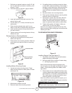
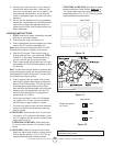
Attaching Mounting Bracket to Wall
Use holes on each end of mounting bracket to attach
bracket to wall. These holes are 16 inches apart. Attach
mounting bracket to wall in one of two following ways.
1. Attach to wall studs
2. Attach to wall anchor
Attaching to Wall Stud:
This way is the best providing the strongest mounting in
wood frame houses.
Attaching to Wall Anchor:
This way allows you to attach mounting bracket to hol-
low walls (wall areas between studs) or to solid walls
(concrete or masonry).
Decide which way best suits your needs. Either method
will provide a secure hold for the mounting bracket.
1. Tape mounting bracket to wall where heater
will be located. Make sure mounting bracket is
level. For wall stud mounting locate one end of
the mounting bracket over a wall stud.
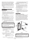
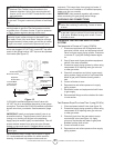
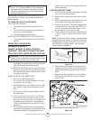
WARNING: Maintain minimum clearances shown in
gure 7. If you can, provide greater clearances from
the oor and joining wall.
2. Mark screw locations on wall (see gure 7).
3. Remove tape and mount bracket from wall.
Figure 7
Attaching to Wall Stud:
For attaching mounting bracket to wall studs
1. Drill holes at marked locations using 9/64” drill
bit.
2. Place mounting bracket onto wall. Line up
holes on each end of bracket with hole drilled in
wall.
3. Insert mounting screws through bracket and
into wall studs.
4. Tighten screws until mounting bracket is rmly
fastened to wall studs.
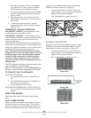
Attaching to Wall using Anchor:
For attaching mounting bracket to hollow walls (wall ar-
eas between studs) or solid walls (concrete or masonry)
Note: Wall anchors, mounting screws, and spacer
are in hardware package. The hardware package is
provided with heater.
Adjoining Wall
17-1/2” Min.
6-1/2” Min. 10,000 BTU
10-1/4” min 20,000-30,000 BTU
16” (Lg)
12-9/64” (Sm)
Mark mounting hole locations
and drill holes where indicated.
Allow for minimum clearances
Left
Side
Right
Side
36” min. from
ceiling
6” Min from
adjoining
walls
2” min. to top surface of carpet, tile
or other combustible material
Floor
Mounting
Bracket