


Installation instructions and Owner’s Manual
7
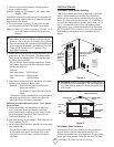
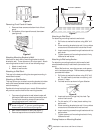
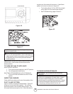
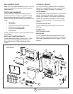
1. Locate two horizontal slots on back pane of
heater (see figure 19).
2. Place heater onto mounting bracket. Slide
horizontal slots onto stand-out tabs on mounting
bracket.
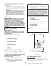
Figure 9
Installing Bottom Mounting Screws
1. Locate two bottom mounting screw holes. These
holes are near bottom on back panel of heater
(see figure 9).
2. Mark screws locations on wall.
3. Remove heater from mounting bracket.
4. If installing bottom mounting screw into hollow or
solid wall, install wall anchors. Follow steps 1
through 4 under Attaching to Wall using Anchor.
If installing bottom mounting screw into wall
stud, drill holes at marked locations using 9/64”
drill bit.
5. Re-place heater onto mounting bracket.
6. Place spacers between bottom mounting holes
and wall anchor or drilled hole.
7. Hold spacer in place with one hand. With the
other hand, insert mounting screw through
bottom mounting hole and spacer. Place tip of
screw in opening of wall anchor or drilled hole.
8. Tighten both screws until heater is firmly se-
cured to wall. Do not over tighten.
Note: Do not re-place front panel at this time.
Re-
place front panel after making gas connections and
checking for leaks.
CONNECTING TO GAS SUPPLY FOR
PERMANENT INSTALLATION
WARNING: A qualified service person must connect
heater to gas supply. Follow all local codes.
WARNING: This appliance requires a 3/8” NPT
(National Pipe Thread) inlet connection to the
pressure regulator.
CAUTION: Never connect heater directly to the Propane
supply. This heater requires an external regulator (not
supplied). Install the external regulator between the heater
and Propane/LP supply.
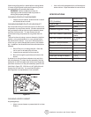
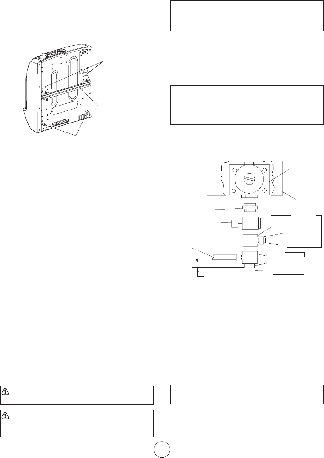
The installer must supply an external regulator. The
external regulator will reduce the incoming gas pressure
to between 11 and 14 inches of water. If you do not
reduce incoming gas pressure heater regulator damage
could occur. Install external regulator with the vent
pointing down as shown in Figure 12. Pointing the vent
down protects it from freezing rain or sleet.
CAUTION: Use only new black iron or steel pipe.
Internally-tinned copper tubing may be used in certain
areas. Check your local codes. Use a large enough
diameter pipe to allow proper gas volume to heater. If
pipe is too small, undue loss of pressure will occur.
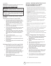
Installation must include an equipment shutoff valve,
union and plugged 1/8” NPT tap. Locate NPT tap within
reach of test gauge hookup.
NPT tap must be upstream
from heater (see figure 12).
Figure 12
*A CSA/AGA certified equipment shutoff valve with 1/8”
NPT tap is an acceptable alternative to test gauge
connection. Purchase the CSA/AGA certified equipment
shutoff valve from your dealer.
IMPORTANT: Install an equipment shutoff valve in an
accessible location. The equipment shutoff valve is for
turning on or shutting off the gas to the appliance.
Apply pipe joint sealant lightly to male threads. This will
prevent excess sealant from going into pipe. Excess
sealant in pipe could result in clogged heater fuel train.
CAUTION: Use pipe joint sealant that is resistant to
LP-Gas.
Install sediment trap in supply line as shown in figure 12.
Locate sediment trap where it is within reach for clean-
ing. A sediment trap traps moisture and contaminants.
This keeps them from going into heater. If sediment trap
is not installed or is installed improperly, heater may not
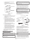
Horizontal Slots
Mounting Bracket
mounted to wall
Pressure
Regulator
Heater
Cabinet
Ground Joint
Union
Equipment
Shutoff Valve
From regulated LP tank
(11”W.C. to 14”W.C.
pressure).)
Tee Joint
1/8” NPT Plug Tap
Cap
Pipe Nipple
Tee Joint
3/8” NPT Pipe Nipple
Sediment
Trap
Test Gauge
Connection
Reducer Bushing
to 1/8” NPT
3” Minimum
Mounting Screws