


8
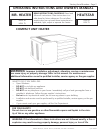
Enerco | Compact Unit Heater Operating Instructions and Owner’s Manual
5. Vent termination must be a minimum of 4’ (1.2m) below or
4’ (1.2m) horizontally from any soft vent or under-eave vent.
6. Vent must be a minimum of 6’ from an inside corner formed
by two exterior walls. If possible, leave a 10’ clearance.
7. Vent termination must be a minimum of 10’ (3m) from any
forced air inlet (includes fresh air inlet for other appliances,
such as a dryer).
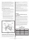
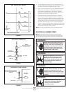
8. When termination is routed through an exterior combustible
wall the vent must be supported using a listed clearance
thimble. Where local authorities permit, a single section
of type B-1 vent pipe may be used as an alternative to the
thimble. When using a type B-1 vent termination use the
clearances specified by the vent manufacturer. Seal the
connection between the single wall and double wall pipes
and the annular space of the double wall pipe as shown in
gure 2. Inside edge of vent termination tee must be at least
12 inches from outside wall as shown in figure 3.
9. For horizontal venting, the vent pipe shall be supported with
hangers no more than 3ft. (1m) apart to prevent movement
after installation.
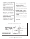
D – HORIZONTAL VENTING – COMMERCIAL
1. Horizontal commercial installations are for buildings which
are not attached to living spaces. The vent may be single wall
vent material installed according to the sections
Venting A - General Recommendations and
Requirements and C - Horizontal Venting General and D -
Horizontal Venting - Commercial. Refer to figure 3.
2. The vent pipe diameter for horizontal commercial installations
shall be 4V” (76mm) on 45 units. In all cases, a ue transition
piece (supplied) is required to fit over the outlet of the
induced draft assembly on the appliance.
3. Refer to table 2 for maximum vent connector lengths.
4. Select a wall termination point that will maintain ¼” rise
per foot slope of horizontal run of vent pipe. The vent
may be single wall material minimum 26 GSG (0.46mm)
galvanized steel or equivalent grade stainless steel. Seal
single wall vent material according to the section A - General
Recommendations and Requirements.
5. For upward sloped vent a condensate tee and drain must
be installed within the first 5’ (1.5m) from the unit heater
to protect the appliance. If a flexible condensate drain line
is used, the drain line must include a loop entering the
structure. If the unit is shut down for an extended period of
time and will be exposed to sub-freezing temperatures, the
condensate may freeze.
E – HORIZONTAL VENTING – RESIDENTIAL
1. For horizontal residential installations these units are
certified as Category I appliances. The vent may be single
wall material minimum 25 GSG (0.46mm) galvanized steel
or equivalent grade stainless steel. Venting A - General
Recommendations and Requirements and C - Horizontal
Venting General and E - Horizontal Venting - Residential.
Refer to figure 6.
2. The vent pipe diameter for horizontal residential installations
shall be 4” (100mm) on 45 units. A standard vent transition is
required at unit in addition to the transition supplied with the
unit.
3. The maximum vent length is 5’ (1.5m) plus one 90-degree
elbow. The minimum length is 3’(.91m).
4. The vent must maintain a ¼” rise per foot of slope upwards
toward the termination.
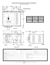
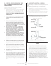
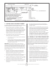
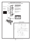
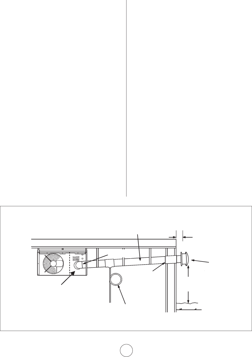
FIGURE 3
COMMON VENTING NOT ALLOWED WHEN HORIZONTALLY VENTING THE UNIT HEATER
CONDENSATE DRAIN THROUGH TEE PIPE AND DRAIN LOOP
UPWARD SLOPE ON HORIZONTAL VENT-COMMERCIAL INSTALLATION
MAY BE SINGLE WALL (26 GSG) GALV. OR EQUIV. STAINLESS STEEL SEALED ACCORDING TO
THESE INSTALLATION INSTRUCTIONS. SLOPE: + 1/4 INCH FOR 1 FOOT RUN MINIMUM.
INDUCED DRAFT BLOWER
DRAIN LOOP WITH WATER
TRAP (TO CONDENSATE DRAIN)
LISTED THIMBLE
THROUGH COMBUSTIBLE
WALL
12 INCHES MIN.
(30.5 CM)
VENT TERMINATION
CAP
NOTE - MINIMUM HORIZONTAL LENGTH 3 FT. (914MM),
NOT INCLUDING CAP FOR TERMINATION. REFER TO TABLE
2 FOR MAXIMUM LENGTH AND NUMBER OF ELBOWS.
12” (30.5 CM)
MINIMUM ABOVE ALL
HIGHEST SNOWFALL
FLUE TRANSITION
(PROVIDED)