


OPERATING INSTRUCTIONS
PREPARING FOR OPERATION
1. Check the heater for possible shipping damage. If any is
found, immediately notify the factory.
2. Follow all of the "Precautions".
3. Connect the POL fitting of hose and regulator assembly to
the propane cylinder by rotating the POL nut
counterclockwise into the propane cylinder's valve outlet and
securely tighten with a wrench.
4. Connect the hose to the heater by rotating the hose fitting
clockwise.
5. Securely tighten all gas connections.
6. Open the cylinder's gas valve and check all gas connections
with a soap and water solution. DO NOT USE A FLAME.
7. Connect power cord to well-grounded 115V, 60 Hz, 1Ø source
of power.
8. When using an extension cord, make certain that it is a 3-
wire (grounded) cord of proper wire size.
START
1. Before heater ignition, always allow heater fan (blower) to
run for 20 seconds to purge fuel.
2. Slowly open the main valve at propane cylinder.
3. Depress the fuel valve button to light the 55FAV, 85FAV and
125FAV models.
4. After the heater lights, keep the gas valve button depressed
for 15 seconds then release and the heater will continue
to operate.
5. Adjust burn rate by setting control knob to desired level.
STOP
1. Securely close valve on the propane cylinder.
2. Continue to operate heater until all fuel in the hose has
burned.
3. Unplug the power cord.
RESTART AFTER SAFETY SHUTDOWN
1. Securely close valve at propane cylinder. Unplug heater.
2. Wait 5 minutes.
3. Restart following "Start" procedure.
MAINTENANCE AND STORAGE
1. The heater should be inspected before each use, and at least
annually by a qualified person.
2. Before each use, check the soft "O" ring seat at the bullnose
of the POL fitting. If the "O" ring is cut, scuffed, or otherwise
damaged, replace it with part number 73786.
3. Turn off the gas at the LP-gas supply cylinder(s) when
the heater is not in use.
4. When the heater is to be stored indoors, the connection
between the LP-gas supply cylinder(s) and the heater must be
disconnected and the cylinder(s) removed from the heater
and stored out of doors and in accordance with Chapter 5 of
the standard for Storage and Handling of Liquefied Petroleum
Gases ANSI/NFPA 58 and CSA B149.1, Natural Gas and
Propane Installation Code.
SERVICING
A hazardous condition may result if a heater is used that has been
modified or is not functioning properly. When the heater is
working properly:
• The flame is contained within the heater.
• The flame is essentially blue with perhaps some yellow
tipping.
• There is no strong disagreeable odor, eye burning or other
physical discomfort.
• There is no smoke or soot internal or external to the heater.
• There are no unplanned or unexplained shut downs of the
heater.
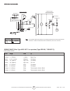
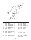
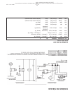
The parts lists and wiring diagram show the heater as it was
constructed. Do not use a heater which is different from that
shown. In this regard, use only the hose, regulator and cylinder
connection fitting (called a POL fitting) supplied with the heater.
IMPORTANT Match the color stripe on the hangtag attached to
the hose assembly with the color on the label located near the
propane inlet fitting on the heater. Do not use alternates. For this
heater, the regulator must be set as shown in "specifications". If
there is any uncertainty about the regulator setting, have it
checked.
A heater which is not working right must be repaired, but only by
a trained, experienced service person.
In-warranty products will be repaired with no charge for either
parts or labor. Please include a brief statement indicating date,
place of purchase, the nature of the problem and proof of
purchase.
Out-of-warrranty products will be repaired with a charge for parts
and labor.
6
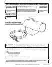
Operating Instructions and Owner’s ManualEnerco Group, Inc.| Forced Air Propane Construction Heater
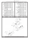
Heater Elevation Adjustment
This heater is equiped with an elevation adjustment panel
located at the exhaust end of the control box.
1. Do not adjust the heater combustion tube elevation while
heater is running or hot. Adjustments to elevation should
only be made after the heater has cooled to touch.
2. To adjust the heater combustion tube elevation, turn the
adjustment screw knob counterclockwise and lift the
combustion tube to desired position.
70056 Rev. A 5/05