


4
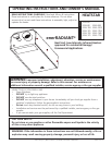
Enerco | enerRadiant® XL Series Heater Operating Instructions and Owner’s Manual
• When installed over hoists, minimum
clearances to combustibles must be main-
tained from the uppermost point on the
hoist.
Electrical: The heater must be electrically grounded in
accordance with the National Electrical Code,
ANSI / NFPA-70 – latest revision. Wiring must
conform to the most current National Electrical
Code, local ordinances, and any special
diagrams furnished.
Venting: The venting must be installed in accordance
with NFPA-54 / ANSI Z223.1 – latest revision,
National Fuel Gas Code. Partial information
with regard to this code is provided in
(Section 5) of this installation manual with
regard to size and congurations for venting
arrangements.
• Any portion of ue pipe passing through
a combustible wall must be dual insulated
or have an approved thimble. Refer to
ANSI-Z223.1 – latest revision.
Hazardous
Locations: Where there is the possibility of exposure to
combustible airborne material or vapor, consult
the local Fire Marshal, the re insurance
carrier or other authorities for approval of the
proposed installation.
Critical Considerations
Ener-Radiant ERXL is a suspended heater.
Therefore, its stability, exibility, and safety are
very important. Before starting installation,
be sure the system can meet the following
requirements.
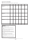
• Maintain specied clearances to combus-
tibles, and safe distance from the heat-
sensitive material, equipment and work
stations.
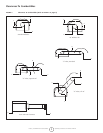
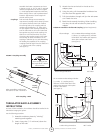
• Provide a suspension with vertical length
of chain or swinging rod which has at
least 2 inches of horizontal travel for
each burner in a straight run. Be sure the
suspension system is sufciently exible to
accommodate thermal expansion which
occurs as the system heats up (see
Figure 5 on page 15).
• Provide access to burners for servicing,
preferable on both sides, above and be-
hind the burner for removal.
• Provide a minimum of 18 inches of clear-
ance between burners and building walls.
(Always observe minimum clearances to
combustibles.)
• Be sure the heater has a downward pitch
of one-half inch per 20 feet away from the
burner.
• Provide signs in storage areas to specify
maximum stacking height to maintain
required clearances to combustibles.
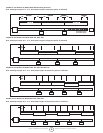
• Plan location supports (see Figure ?).
Locate a support near all elbows.
Installation Procedure
Take maximum advantage of the building
upper structure, beams, joists, purlins, etc.,
from which to suspend the heater. There is no
unique sequence for installation of the tubing.
On-site observation will usually reveal a logical
sequence. Begin the installation at the most
critical dimension. This could save time. Watch
for swinging doors, overhead cranes, car lifts,
etc. Reectors and tubing can be installed as
you move along. Carefully adjust system pitch
at each position to level the heater. Pitch down
one-half inch in 20 feet (away from burner).
Don’t Pressure test the gas line using high pressure
(greater than ½ PSIG) without closing the
high-pressure shutoff cocks. Failure to do so
will result in damage to the burners.
DO Familiarize yourself with local and national
codes.
Develop a planned procedure which will
conserve material and labor on the job.
Check to see that all material and equipment is
on the job before starting installation.
Allow for thermal expansion of the hot tube.
Install the gas connector only as shown in
instructions (see Figure 17).
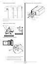
Have slip joints where required between
reectors to keep them from buckling or
coming apart.
Provide 1 sq. inch of free air opening to each
1,000 BTU/hr. of heater input (but not less
than 100 sq. inches) in enclosed spaces. One
opening should be within 12 inches of the top
and one within 12 inches of the bottom of the
enclosure.