


23
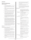
Operating Instructions and Owner’s ManualEnerco | enerRadiant® XL Series Heater
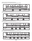
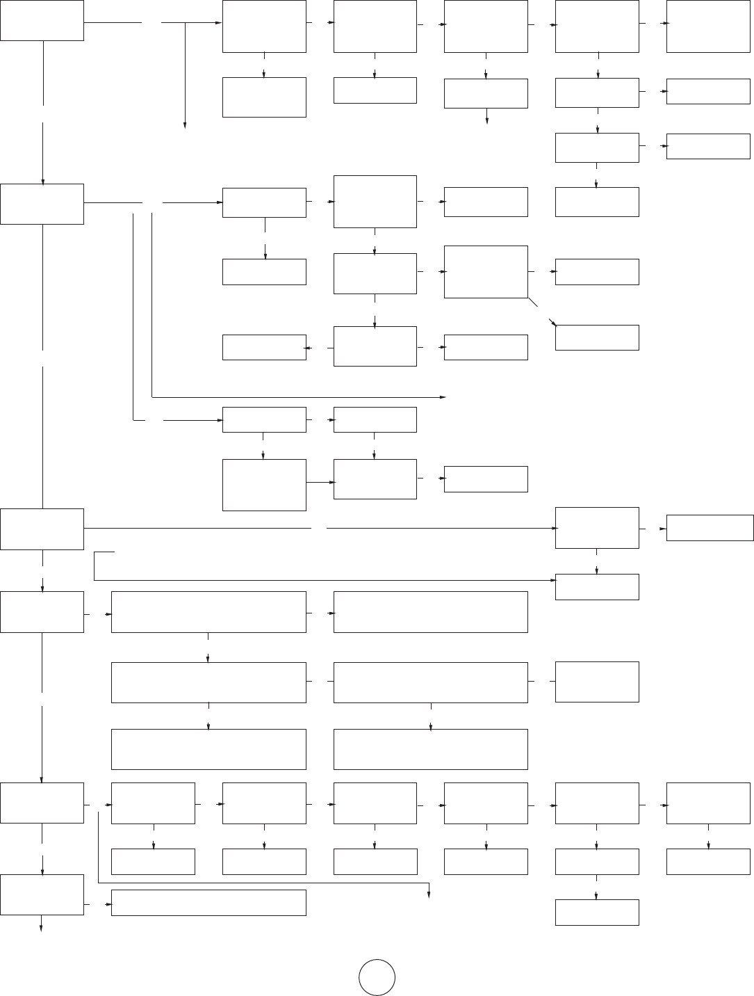
SECTION 8: Troubleshooting Guide. Ener-Radiant XL
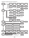
START
Turn on thermostat
Does blower turn
on?
Yes
Does the igniter
warm up and glow
red?
Yes
No
Check Thermostat
and Wiring. Is the
power supply to unit
115V?
No
Find the source
of the electrical
problem
Check LED indicator on SmartValve for
indication of fault. Refer to SmartValve testing
on page ?? to determine problem.
No
Is the air intake or
exhaust blocked?
Yes
Remove Obstruction
Check wiring and
connections
No
Is the ignitor
damaged?
No
Check voltage at
ignitor. Is it 115V
during ignition
cycle?
Yes
Is blower side door
in place?
No
Replace door
No
Check wiring and
hose connection to
air switch. Are they
OK?
Yes
Is the voltage at
the transformer
secondary 24V?
No
Is the voltage at the
transformer primary
115V
Replace ignitor.
Yes
No
Is the resistance
through igniter 40
to 75 ohms?
Remove door. Is
voltage at door
switch 115V?
Yes
No
Check voltage at
gas valve.
Check for 115V transformer input at plug C3
on SmartValve. Check for 115V output of
C3. If no output voltage is present replace
SmartValve.
Replace wiring and/
or hose connection.
No
Jumper wires at
pressure switch.
Does the ignitor
glow red?
Yes
Replace transformerYes
Check wire
connections.
Yes
Depress switch.
Does blower come
on?
Yes
Yes
No
Check voltage to
motor. Is it 115V?
Yes
Is the blower fan
obstructed?
No
Replace blower
motor.
Replace pressure
switch.
Yes
Replace SmartValve.
No
Check LED indicator on SmartValve for
indication of fault. Refer to SmartValve testing
on page ?? to determine problem.
Check door t. If
damaged, replace
door.
Replace switch.
No
Remove obstruction
Yes
After ignitor warm-
up period, does the
valve click?
Yes
Does the burner
light?
Yes
Does the burner
stay on?
Yes
Does the burner
run until the call
for heat ends?
If a problem still exists, contact Enerco Technical Products Customer Service
1-800-251-0001
No
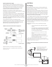
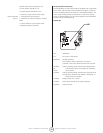
The SmartValve checks the status of the blower proving switch contacts must see a change in the
contact with every ring cycle. Placing a jumper at the switch out of sequence will result in a fault with
the LED indicator ashing two times.
Were the gas lines purged of air?
No
No
Yes
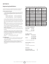
Check inlet gas pressure. Is pressure correct?
Refer to page 40 for correct pressure for unit.
Yes
Check inlet gas shutoff. Adjust regulator.
Contact gas supplier
Is the continuity of
the ground wire
OK?
No
The switch on the gas valve must be in the on
position and the line purged of air.
No
Repair wiring.
No
Check the continuity of the ground wire.
Check the thermostat.
Check outlet gas pressure during ignition cycle.
Is the pressure 3.5” w.c. for natural or 10.5”
w.c. for lp?
Yes
Adjust to proper pressure.
No
Are L1 and L2
reversed?
Yes
Yes
Repair wiring
Is the wiring at the
SmartValve OK?
No
Repair wiring
Is the insulation on
the sensor lead OK?
No
Repair wiring
No
Yes
Yes
Are the wires to
the SmartValve OK?
Yes
Replace SmartValve
No
Replace/repair wires.
Yes
Check for proper
burner orice and
air plate.
Is the sensor
positioned
properly?
Yes
Is the sensor dirty?
No
Replace Sensor
No
Repair/Replace
Yes
Clean sensor.
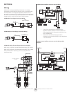
A fault indication of six ashes may indicate
that the ame sensing circuit is not functioning
properly. Perform the following series of checks
to correct the problem.
No