


16
Enerco | enerRadiant® XL Series Heater Operating Instructions and Owner’s Manual
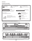
SECTION 4
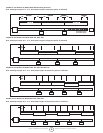
Venting / Ducting
General Requirements
Heater must be vented in accordance with specication ANSI Z223.1
- latest revisions. Partial information relating to this specication is
provided in this section with regard to size and congurations for
venting arrangements (see Figures 12, 13, 14, 15, 16). For complete
information consult ANSI Z223.1 - latest revision and applicable local
codes. Use the following guidelines to help insure an adequate, safe
venting arrangement.
a) Be sure that method selected for venting
heater complies with all codes as required for
each particular location.
b) Exhaust end of heater will accept a four (4”)
inch ue pipe using the ue pipe adapter.
c) Heater may be vented to the outdoors either
vertically or horizontally.
d) If heater is to be vented horizontally:
1) Vent must exit building not less than seven (7’)
feet above grade when located adjacent to public
walkways.
2) Vent must terminate at least three (3’) feet above
any forced air inlet located within ten feet (10’).
3)Vent must terminate at least four (4’) feet below,
four (4’) feet horizontally from, or one (1’) foot
above any door, window, or gravity inlet into any
building.
4) Vent terminal shall be located at least twelve (12”)
inches from any opening through which vent gases
could enter the building.
e) Vent terminal must be beyond any combustible
overhang.
f) If condensation in the ue is a problem, the
ue length should be shortened or insulated.
g) For vent specications all of the following
conditions must be met.
1) Maximum total vent length allowed in forty-five
(45’) feet.
2) Maximum outside air supply duct allowed forty-five
(45’) feet.
3) Maximum total vent length plus outside air supply
length plus extension package shall not exceed sixty
-five (65’) feet.
4) Under length conditions 1) through 3) above — a
total of two (2) elbows are allowed for vent and
outside air supply together. Subtract fifteen (15’)
feet per additional elbow from maximum length
allowed if more than two (2) elbows are used.
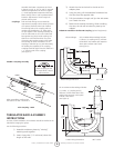
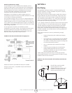
Alternative Arrangements / Optional Equipment for Venting
Unvented Operation
a) Sufcient ventilation must be provided in the
amount of 4 CFM per 1,000 BTU/hr. ring rate.
b) Refer to ANSI Z223.1 - latest revision, NFPA-54
and local codes for additional information.
c) Use of optional outside combustion air is not
recommended with unvented heaters due to
pressure considerations.
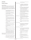
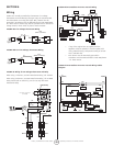
Horizontal Venting
a) In combustible or noncombustible walls,
use Tjerblund VH1-4” (Stk. #19022). Follow
vent manufacturer’s instructions for proper
installation. (Alternative vent Enerco Stk.
#19023).
b) Four (4”) inch O.D. ue pipe is required. Thirty
(30’) feet maximum length is recommended.
Up to forty-ve (45’) feet maximum may
be used if insulated to prevent excess
condensation. (See General Requirements on
page 21 for additional information).
c) All ue joints should be sealed using suitable
product such as General Electric RTV106 or
Permatex Form-A-Gasket Red High Temperature
Silicone Adhesive Sealant.
d) Vent terminal should be installed at a height
sufcient to prevent blockage by snow.
e) Building materials should be protected from
degradation by ue gases.
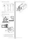
Vertical Venting a) Four (4”) inch O.D. ue pipe, maximum
forty-ve (45’) feet in length may be used as
shown with approved vent cap. (See General
Requirements on page 21 for additional
information.)
b) An insulated thimble may be required to pass
through combustible structures (check local
codes).
c) All ue joints should be sealed using suitable
products (see recommendation for horizontal
venting.)
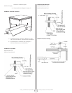
Draft Hood Venting
a) Refer to ANSI Z223.1 - latest revision, NFA-54
for heights and vent sizes recommended
for proper venting. (Check local codes for
additional information.)
b) Minimum six (6”) inch O.D. vent is
recommended.
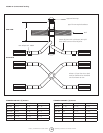
Common Venting
a) Horizontal run to vent must never exceed 75%
of the vertical height of the vent. Refer to ANSI
Z223.1 - latest revision, NFA-54 for proper vent
sizes and installation.
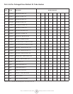
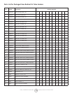
b) Open area of common vent must equal the
sum of the open area of individual vents
connected to it. (See chart and diagrams -
page 25.)
c) Use double wall vent as required (check
codes.)
d) Heaters sharing a common vent must be
controlled by the same thermostat.
e) All joints must be sealed using suitable
products (see recommendation for horizontal
vent - page 24.)
f) Connections to common stack must be
positioned to avoid direct opposition between