


12822-2-0903 Page 5
INTRODUCTION
Introduction
Always consult your local Building Department regarding
regulations, codes or ordinances which apply to the installation of
a vented room heater.
Instructions to Installer
1. Installer must leave instruction manual with owner after
installation.
2. Installer must have owner fill out and mail warranty card
supplied with heater.
3. Installer should show owner how to start and operate heater
and thermostat.
General Information
This series is design certified in accordance with American
National Standard/CSA Standard Z21.86 and CSA 2.32 by the
Canadian Standards Association, as a Vented Room Heater
and must be installed according to these instructions.
Any alteration of the original design, installed other than
as shown in these instructions or use with a type of gas not
shown on the rating plate is the responsibility of the person
and company making the change.
Important
All correspondence should refer to complete Model Number,
Serial Number and type of gas.
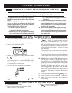
Notice: During initial firing of this unit, its paint will bake out and
smoke will occur. To prevent triggering of smoke alarms, ventilate
the room in which the unit is installed.
Installation on Rugs and Tile
If this appliance is to be installed directly on carpeting, tile, or
other combustible material, other than wood flooring, the appliance
shall be installed on a metal or wood panel extending the full width
and depth of the appliance.
The base referred to above does not mean the fire-proof base as
used on wood stoves. The protection is primarily for rugs that may
be extremely thick and light-color tile that can discolor.
Floor pad is available from Empire Comfort Systems, Inc., Part
Number RH-425.
Qualified Installing Agency
Installation and replacement of gas piping, gas utilization
equipment or accessories and repair and servicing of equipment
shall be performed only by a qualified agency. The term
"qualified agency" means any individual, firm, corporation,or
company which whether in person or through a representative
is engaged in and is responsible for (a) the installation or
replacement of gas piping or (b) the connection, installation,
repair or servicing of equipment, who is experienced in such
work, familiar with all precautions required and has complied
with all the requirements of the authority having jurisdiction.
State of Massachusetts: The installation must by made by a
licensed plumber or gas fitter in the Commonwealth of
Massachusetts
The installation must conform with local codes, or in the
absence of local codes, with the National Fuel Gas Code, ANSI
Z223.1*/ Canadian Installation Code,CAN/CGA B149.
*Available from the American National Standards Institute, Inc., 11 West
42nd St., New York, N.Y. 10036.
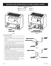
High Altitudes
For altitudes/elevations above 2,000 feet (610m), input ratings
should be reduced at the rate of 4 percent for each 1,000 feet
(305m) above sea level. Canadian High Altitudes for locations
having an elevation above mean sea level between 2,000 feet
(610m) and 4,500 feet (1370m), the manifold pressure is to be
decreased from 4.0" w.c. (.996kPa) to 3.2" w.c. (.797kPa) for
Natural Gas and from 10.0" w.c. (2.49kPa) to 8.0" w.c. (1.99kPa)
for Propane Gas.
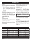
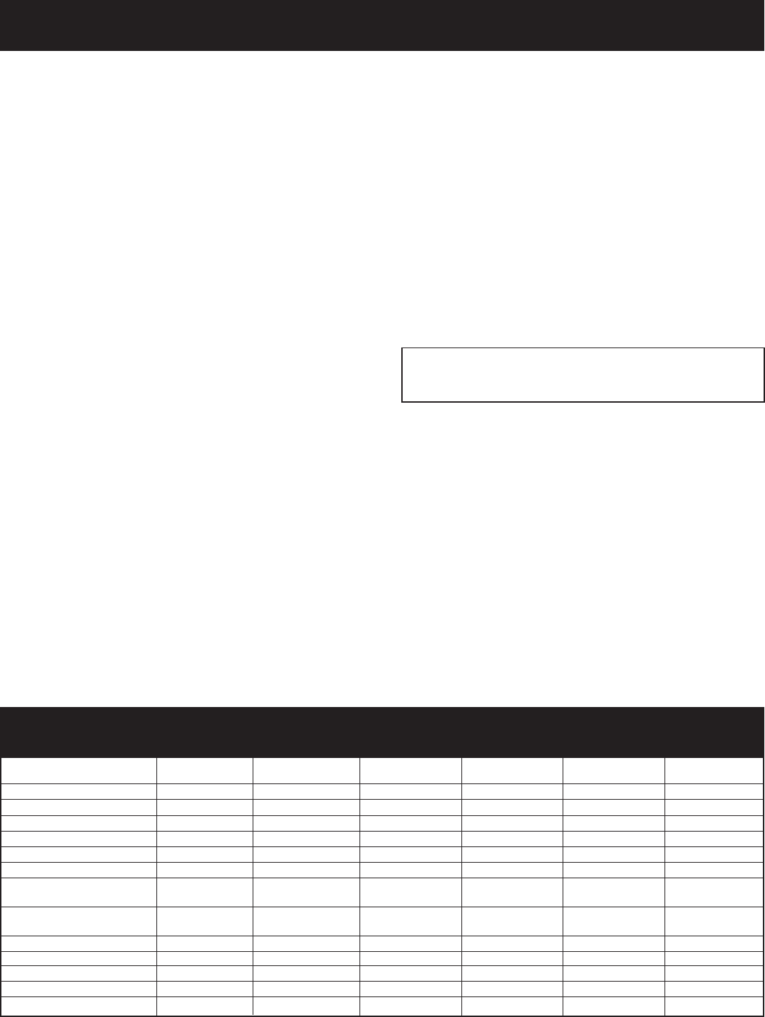
SPECIFICATIONS
Models RH-50B RH-65B RH-50C RH-65C RH-50CB RH-65CB
Input BTU/HR (KW/H) 50,000 (14.6) 65,000 (19) 50,000 (14.6) 65,000 (19) 50,000 (14.6) 65,000 (19)
Height 29 9/16" (751mm) 29 9/16" (751mm) 29 9/16" (751mm) 29 9/16" (751mm) 29 9/16" (751mm) 29 9/16" (751mm)
Width 34" (864mm) 34" (864mm) 34" (864mm) 34" (864mm) 34" (864mm) 34" (864mm)
Depth including diverter 23 3/16" (589mm) 27 11/16" (704mm) 23 3/16" (589mm) 27 11/16" (704mm) 23 3/16" (589mm) 27 11/16" (704mm)
Gas Inlet 1/2" (13mm) 1/2" (13mm) 1/2" (13mm) 1/2" (13mm) 1/2" (13mm) 1/2" (13mm)
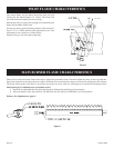
Size Draft Diverter Collar 5 " (127mm) 5 " (127mm) 5 " (127mm) 5 " (127mm) 5 " (127mm) 5 " (127mm)
Floor to top of collar on vertical
position of Draft Diverter 27 5/32" (690mm) 27 5/32" (690mm) 27 5/32" (690mm) 27 5/32" (690mm) 27 5/32" (690mm) 27 5/32" (690mm)
Floor to center of collar on horizontal
position of Draft Diverter 22 9/16" (573mm) 22 9/16" (573mm) 22 9/16" (573mm) 22 9/16" (573mm) 22 9/16" (573mm) 22 9/16" (573mm)
Accessories
Blower Package Included Included FRB-3 FRB-3 Included Included
Radiant Package RAD-8 RAD-8 N/A N/A N/A N/A
Floor Pad RH-425 RH-425 RH-425 RH-425 RH-425 RH-425
Ceramic Log RHL-1 RHL-1 N/A N/A N/A N/A