


Page 6
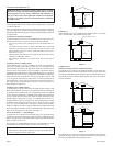
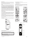
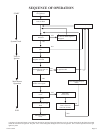
Figure 5
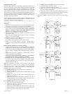
Use U.L. listed gas vent equipment when installing the FAW-40. For
vent pipe running through walls, roof, and within one (1) inch (25mm) of
combustible construction, use B-1 or (B-W) [one inch (25mm) clearance
to combustibles] vent pipe. Type B-2 x 4 or Type B-2 x 6 are to be used
in conjunction with a Listed fire stop spacer.
Be sure baseplate is attached to top of furnace before inserting unit into
recessed wall installation.
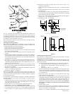
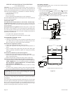
Installing Optional Side Outlets
Side outlet register,
SOR-1 may be installed on one or both sides of the
furnace at the required clearances of 18 inches (457mm) to adjacent wall
or combustible material as shown in Figure 6.
1. Turn "OFF" all electric power to the furnace.
2. Remove the front panel from the furnace.
3. Remove the (2) #8 x 3/8" (9mm) screws that attach the inner shield
cover plate to the inner shield.
4. Scribe a line between the four dimples on the outer casing side to form
a square.
5. Drill a pilot hole within the scribed square on the outer casing. Remove
the sheet metal within the scribed square with a tin snips or comparable
tool. Attention! Do not cut the electrical wires located between the outer
casing and the inner shield.
6. Insert the 5" x 5" (127mm x 127mm) inner boot through the outer cas
-
ing. Align the clearance holes on the inner boot with the screw holes
on the inner shield. Attach inner boot to inner shield with (2) # 8 x 3/8"
(9mm) screws removed in Step 3.
7. Place the register over the 5 1/2" (140mm) square opening with the
louvers set for the desired direction and mark the mounting holes using
the register as a template.
8. Drill (2) 1/8" diameter holes in cabinet side and attach the register with
(2) #10 x 1" (25mm) provided screws.
9. Installation of SOR-1 is completed.
Side outlet kit,
SOK-1, 10" (254mm) boot assembly with register, for
warm air discharge into an adjoining room may be installed on either side
of the furnace at the required clearance of 4 inches (102mm) to adjacent
wall as shown in Figure 6.
To install SOK-1, please use Steps 1 through 5 in the SOR-1 instructions
for FAW-40 furnaces. Now, use the following Steps to complete installa
-
tion of the SOK-1.
1. Using the inner and outer boots as hole templates, mark and drill (4)
1/8" (3mm) diameter holes in the inner shield and (4) 1/8" (3mm)
diameter holes in the cabinet side.
2. Locate and cut a 6 3/4" (171mm) square opening through wall.
3. Attach furnace to wall (see Attaching Furnace to Wall
).
4. With furnace in place, after checking alignment of side outlet opening
in wall and furnace, place the 9 3/8" x 9 3/8" (238mm x 238mm) side
outlet wall plate over outer boot, pass the outer boot through the wall
and attach side wall plate to furnace side of wall with (2) #10 x 1 1/2"
(38mm) provided screws.
5. Attach outer boot to the cabinet side with (4) #8 x 1/4" (6mm) provided
screws.
6. Position and attach inner boot to inner shield with (4) #8 x 1/4" (6mm)
provided screws.
7. Place the register over the 6 3/4" (171mm) square opening with the louvers
positioned for the desired discharge direction and mark the mounting
holes using the register as a template.
8. Drill (2) 1/8" (3mm) diameter holes in the wall and attach the register
with (2) #10 x 1 1/2" (38mm) provided screws.
9. Installation of SOK-1 is completed.
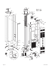
4" MINIMUM TO COMBUSTIBLE�
WALL OR SURFACE
CLEARANCE FOR SIDE OUTLET KITS AND REAR REGISTER�
KIT TO ADJACENT WALL
4" MINIMUM TO COMBUSTIBLE�
WALL OR SURFACE
18" MIN. CLEARANCE TO
WALL OR COMBUSTIBLE
SURFACE USING MODEL
SOR-1 SIDE REGISTER.
WALL
5 1/2"
5 1/2"
UNIT CANNOT BE RECESSED�
WHEN SIDE REGISTERS ARE�
USED.
WHEN SIDE REGISTERS ARE�
NOT USED UNIT MAY BE RECESSED�
UP TO 9 1/2"
6 1/4"
10 1/4"
REAR REGISTER OPENING�
IN OUTER CABINET
12"
12"
TYPE B-1 OR
B-W OVAL�
VENT PIPE
Figure 6
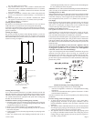
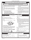
Installing Optional Rear Outlet
Rear outlet kit, 10" (254mm) boot assembly with register, ROK-1 for warm
air discharge into an adjoining room.
Attention: Before furnace is attached to the wall, the wall opening for the
rear outlet must be cut, in addition to removal of the outer and inner casing
knockouts on furnace.
1. The wall opening measurements for the rear outlet are the following.
A. From floor to bottom of wall opening is 10 11/16" (271mm).
B. From bottom of wall opening to top of wall opening is 8 1/2"
(216mm).
C. Wall opening width is 12 1/8" (308mm).
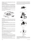
2. Scribe a line between the four dimples on the outer casing back to form
a square. Drill a pilot hole within the scribed square on the outer casing
back. Remove the sheet metal within the scribed square with a tin snips
or comparable tool.
3. Remove the (4) #8 x 3/8" (9mm) screws that attach the inner casing
close off plate to the inner casing.
4. Insert the privacy shield through the outer casing back and the inner
casing back. The privacy shield will be in front of the inner casing back
and behind the combustion chamber tubes. Align clearance holes on
privacy shield with screw holes on inner casing back. Attach privacy
shield to inner casing back with (2) #8 x 3/8" (9mm) provided. Attention:
The (2) #8 x 3/8" (9mm) screws must be inserted from the front of
the furnace.
5. Attach furnace to wall.
6. Align clearance holes on 8" x 12" (203mm x 305mm) boot with screw
holes on outer casing back and mark boot to be flush with wall surface.
Remove boot and cut to proper length.
7. Attach 8" x 12" (203mm x 305mm)boot to outer casing back with (6)
12427-6-0707