


Page 18 17375-6-0705
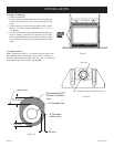
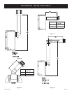
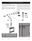
VENTING FIREPLACE - REAR
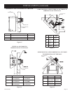
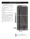
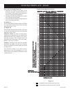
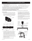
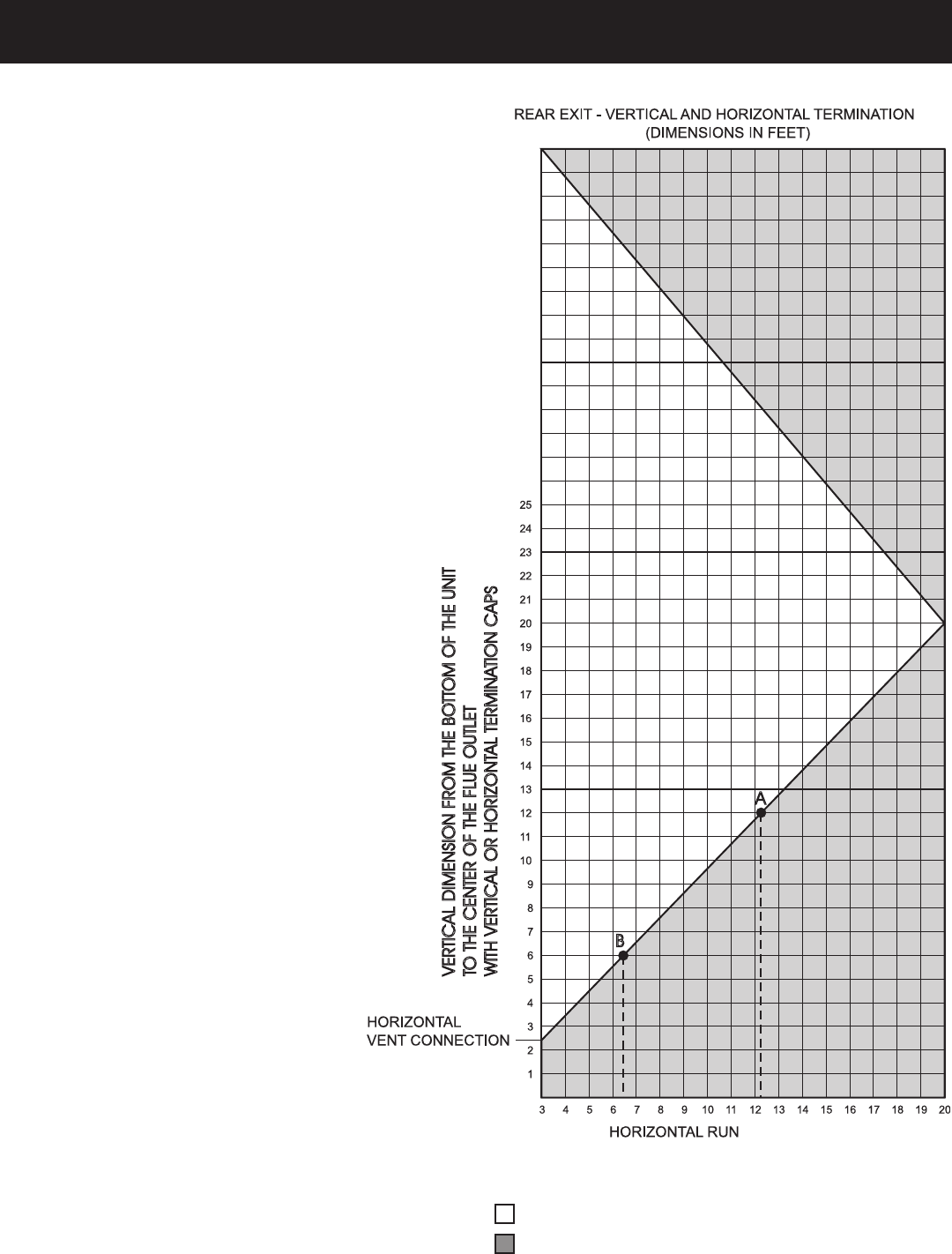
To Use the Vent Graph (Figure 29)
1. Determine the height of the center of the
horizontal vent pipe. Using this dimension on
the Sidewall Vent Graph, locate the point it
intersects with the slanted graph line.
2. From the point of this intersection, draw a vertical
line to the bottom of the graph.
3. Select the indicated dimension, and position the
unit in accordance with same.
EXAMPLE A:
If the vertical dimension from the floor of the unit
is 12 feet, the horizontal run to the outer wall flange
must not exceed 12.3 feet.
EXAMPLE B:
If the vertical dimension from the floor of the unit
is 6 feet, the horizontal run to the outer wall flange
must not exceed 6.5 feet.
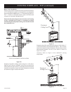
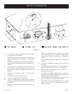
SPECIAL NOTE: For each 45 degree elbow
installed in the horizontal run, the length of the
horizontal run MUST be reduced by 18" (45cm).
This does not apply if the 45 degree elbows are
installed on the vertical part of the vent system.
Reduce 3' for every 90° elbow.
Example: According to the chart the maximum
horizontal vent length is 20' and if two 45 degree
elbows are required in the horizontal vent it must
be reduced to 17'.
The maximum number of 45 degree elbows
permitted per side wall installation is two (2).
These elbows can be installed in either the vertical
or horizontal run.
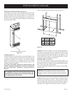
Figure 29
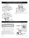
Acceptable vertical and horizontal vent run.
Unacceptable vertical and horizontal vent run.
Venting Graph (Dimensions in Feet)
VERTICAL
DIMENSION
FROM
THE
BO
TTOM
OF
THE
UNIT
TO
THE
CENTER
OF
THE
FL
UE
OUTLET
WITH
VERTICAL
OR
HORIZONT
AL
TERMINA
TION
CAPS
26
27
28
29
30
31
32
33
34
35
36
37
38
39
40
B
A