


23015-3-0707Page 14
ALTERNATE ON/OFF SWITCH INSTALLATION
WIRING THE FIREPLACE
Note: Electrical wiring must be installed by a licensed electrician.
CAUTION: DISCONNECT REMOTE CONTROLS IF YOU ARE AB-
SENT FOR EXTENDED TIME PERIODS. THIS WILL PREVENT
ACCIDENTAL FIREPLACE OPERATION.
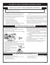
Installation of Alternate Surround Panel ON/OFF Switch
An ON/OFF switch and wire assembly are provided. They are included
in the instruction packet.
Do not cut wire or insulation on metal edges.
Note: Refer to surround panel installation section on page 15 for ad-
ditional information on attachment.
Contemporary Surrounds
1. Find the coiled low voltage wire assembly and ON/OFF switch lo
-
cated in the instruction packet.
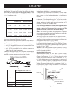
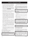
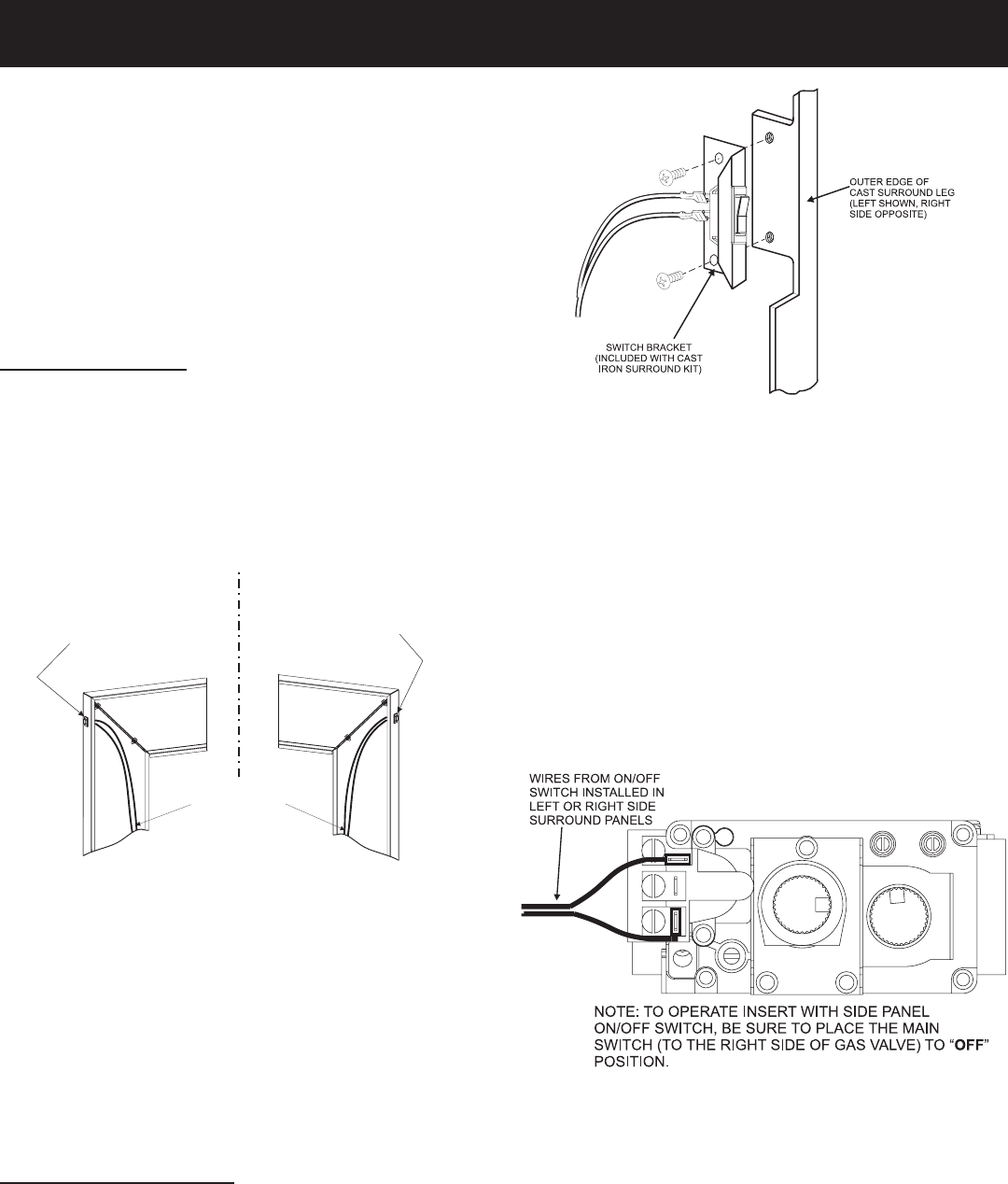
2. Attach the flag terminal ends to the “TH/TP” and “TH” terminals on
the front terminal block of the gas valve. See Figure 13.
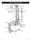
3. Run the low voltage alternate switch wires up the back of the right
or left surround panel. Then secure the wires with wire clips pro
-
vided. See Figure 11.
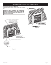
Figure 11
Insert ON/OFF switch into side panel then attach wire assembly
from valve terminals.
4. Remove the switch knockout on the side surround panel, then install
the ON/OFF switch.
5. Connect the low voltage wires from the gas valve to the
ON/OFF switch.
6. Attach the surround panel assembly to the insert. Place the surround
panel assembly against the face of the insert and align the lower
retaining tabs with the notches on the insert sides. Lift the surround
panel assembly slightly until the bottom return flange (top panel)
is positioned over the top flange on the insert. This secures the sur-
round panel assembly to the insert without screws.
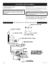
Traditional Cast Iron Surrounds
1. Find the coiled low voltage wire assembly and ON/OFF switch lo
-
cated in the instruction packet.
2. Attach the flag terminal ends to the “TH/TP” and “TH” terminals on
the front terminal block of the gas valve. See Figure 13.
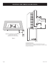
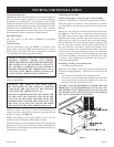
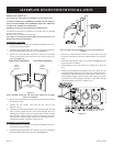
WIRING FROM
MILLIVOL
T GAS
VALV
E
ON/OFF
SWITCH
ASSEMBLY
Right Side Installation
Left Side Installation
ON/OFF
SWITCH
ASSEMBL
Y
Figure 12
Note: For right side leg installation, reverse switch position in
bracket.
3. Run the low voltage alternate switch wires up the back of the right
or left cast surround leg. Then secure them with the wire clips pro
-
vided.
4. Install the switch bracket with screws as shown in Figure 12 to the
back of the cast surround leg.
5. Install ON/OFF switch, and connect low-voltage wires from gas
valve.
6. Attach cast surround panel assembly to the insert. Place the cast
surround assembly against the face of the insert and align the lower
retaining tabs with the notches on the insert sides. Lift the cast sur
-
round assembly slightly until the bottom return flange (top panel)
is positioned over the top flange on the insert. This secures the cast
surround assembly to the insert without screws.
Figure 13