


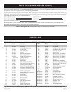
12434-3-0903
Page 15
OPTIONAL BLOWER DRB-1
Vented Room Heaters RH-25-(1, 2, 4, 5, 6) and RH-35-(1, 2, 4, 5, 6)
Direct Vent Wall Furnaces DV-25-(1, 2)SG and DV-35-(1, 2)SG
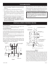
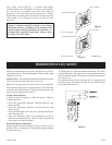
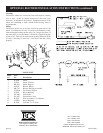
Installing Optional DRB-1 Blower
1. For RH-25-(1, 2, 4, 5, 6) and RH-35-(1, 2, 4, 5, 6), remove
casing front.
1. For DV-25-(1, 2)SG and DV-35-(1, 2)SG, remove casing
front and heat shield.
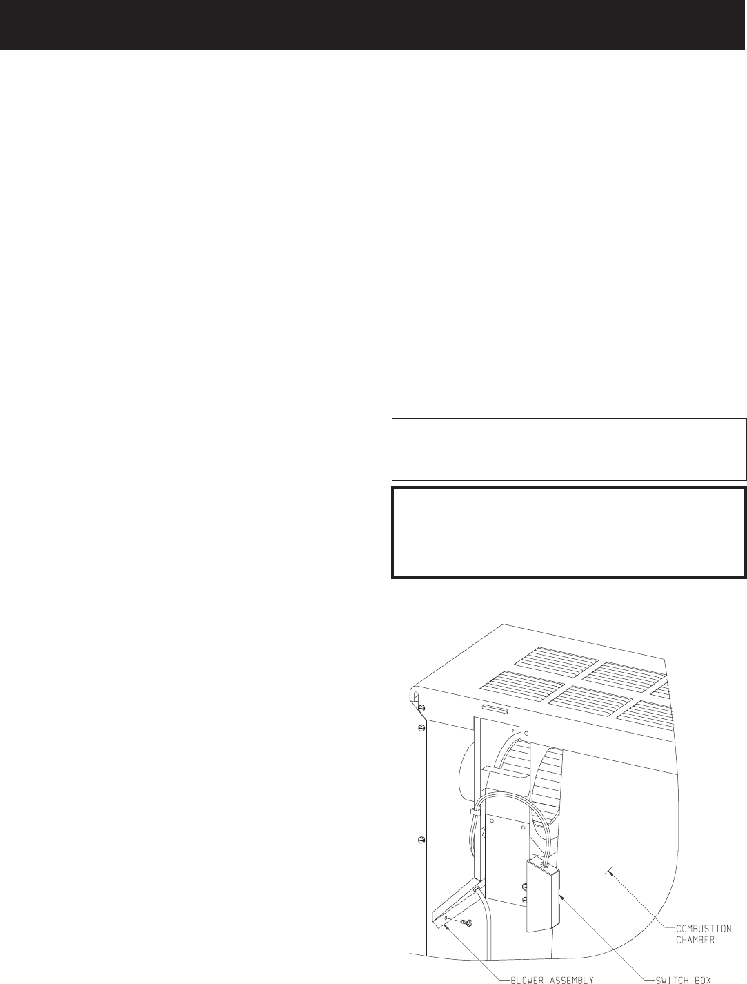
2. When facing appliance, insert blower assembly into the left
section of the casing (adjacent to the combustion chamber).
3. For RH-25-(1, 2, 4, 5, 6) and RH-35-(1, 2, 4, 5, 6), route
cord set through opening in casing back. The opening in
casing back is located adjacent to gas control.
3. For DV-25-(1, 2)SG and DV-35-(1, 2)SG, route cord set
through opening in casing bottom. The opening in casing
bottom is located beneath gas control.
4. Align the (2) screw holes on the inner side panel and the (2)
screw holes on casing back with the (4) clearance holes on
the blower assembly. Attach blower assembly to the casing
back and inner side panel with (4) #10 x 1/2" (13mm)
screws provided. The blower assembly must be attached
first to the casing back and then to the casing side panel.
5. For RH-25-(1, 2, 4, 5, 6) and RH-35-(1, 2, 4, 5, 6), replace
casing front.
5. For DV-25-(1, 2)SG and DV-35-(1, 2)SG, replace heat
shield and casing front.
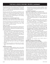
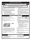
Attention: Wiring harness on blower is factory assembled
and installed. If wiring harness becomes disassembled use the
following steps to reassemble the wiring harness.
1. Attach (1) pin terminal from black (hot) wire, smooth
insulation on cord set to (1) socket terminal on fan control
assembly.
2. Attach (1) pin terminal from black (neutral) wire, ribbed
insulation on cord set to (1) socket terminal from white
(neutral) wire on motor.
3. Attach (1) pin terminal on fan control assembly to (1)
socket terminal from black (hot) wire on motor.
4. Attach green ground wire beneath one of the #10 x 1/2"
(13mm) screws on the blower housing.
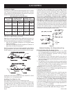
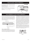
Fan Control
The automatic fan control is located in the switch box. The
switch box is attached to the front of the blower assembly.
The switch box is adjacent to the combustion chamber. The
fan control is a non-adjustable automatic type. The fan control
will require between 5 and 10 minutes of main burner operation
before the fan control "closes" and activates the blower. The
blower will continue to run between 5 and 10 minutes after the
main burner shuts off, before the fan control "opens" and
deactivates the blower.
Wiring
The appliance, when installed, must be electrically grounded in
accordance with local codes or, in the absence of local codes, with
the National Electrical Code, ANSI/NFPA 70 or Canadian
Electrical Code, CSA C22.1, if an external electrical source is
utilized. This appliance is equipped with a three-prong
[grounding] plug for your protection against shock hazard
and should be plugged directly into a properly grounded
three-prong receptacle. Do not cut or remove the grounding
prong from this plug. For an ungrounded receptacle, an
adapter, which has two prongs and a wire for grounding, can
be purchased, plugged into the ungrounded receptacle and its
wire connected to the receptacle mounting screws. With this
wire completing the ground, the appliance cord plug can be
plugged into the adapter and be electrically grounded.
CAUTION: Label all wires prior to disconnection when
servicing controls. Wiring errors can cause improper and
dangerous operation. Verify proper operation after servicing.
WARNING:
Unplugging of blower accessory will not stop the heater
from cycling. To shut heater off: Turn temperature
dial or thermostat to lowest setting. Turn knob on gas
control to "OFF", depressing slightly. Do not force.
OPTIONAL BLOWER INSTALLATION INSTRUCTIONS