


Page 16 16934-3-0806
WIRING
Label all wires prior to disconnection when servicing controls.
Wiring errors can cause improper and dangerous operation.
Verify proper operation after servicing.
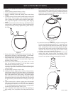
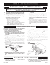
Control Panel Installation
1. Disconnect black and green wire from TH/TP and TH terminal
on valve.
2. Insert REMOTE/OFF/ON switch with attached wires through
rectangular opening on cover plate.
3. Attach black and green wire to TH/TP and TH terminal on
valve.
4. Attach cover plate to valve bracket with two (2) 8 x 1/2" Truss
-head Phillips screws.
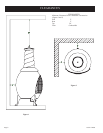
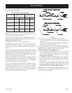
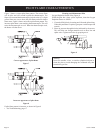
Millivolt) thermopile is self powered gas valve and does not
require 110 volts. See Figure 10 to provide optional wall switch,
thermostat, or remote control. Maximum length of 20 feet of
16 AWG to conductor wires is to be used with all optional
switches.
Use the two leads (black/red wires and brown wires) from
REMOTE/ON/OFF switch to attach optional components.
Check System Operation
Millivolt system and all individual components may be checked
with a millivolt meter 0-1000 MV range.
Remote Receiver
Figure 10
1. The remote receiver can be placed behind the gas valve on
under side of chimenea.
2. Attach remote receiver to the flat bottom of casing behind gas
valve on underside of chimenea.
Refer to remote control installation and operating instructions for
more details on remote control.
750 Millivolt System
When you ignite the pilot, the thermocouple produces millivolts
(electrical current) which energizes the magnet in the gas valve.
After 30 seconds to 1 minute time period you can release the gas
control knob and the pilot will stay ON. Allow your pilot flame to
operate an additional one (1) to two (2) minutes before you turn the
gas control knob from the PILOT position to the ON position. This
time period allows the millivolts (electrical current) to buildup to
a sufficient level allowing the gas control to operate properly.
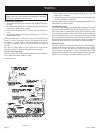
Millivolt Control
The valve regulator controls the burner pressure which should be
checked at the pressure test point. Turn captured screw counter
clockwise 2 or 3 turns and then place tubing to pressure gauge
over test point (Use test point “A” closest to control knob). After
taking pressure reading, be sure and turn captured screw clockwise
firmly to re-seal. Do not over torque. Check for gas leaks.