


12429-10-0408Page 8
Figure 6
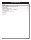
Electrode and pilot must be kept clean. Clean through pilot access
hole with a small brush (toothbrush) and water.
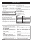
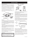
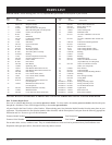
Proper Main Burner Flame
The correct flame will be a short blue inner flame with a much
larger light blue outer flame. The main burner (Figure 7) shows the
approximate height of each part of the flame for each gas. The burner
does not have a primary air adjustment. The flame will be correct if
the factory-set pressure and orifice opening are used. After the furnace
has been operating, the burner ports may be blocked by foreign matter
carried in by combustion air. Therefore, cleaning of the burner may
be needed for proper flame.
To clean burner port disconnect the gas supply to the valve, and remove
the eight screws fastening the burner door. After removing the burner
door from the combustion chamber, remove rear burner, pilot burner
and front burner. With front and rear burners removed from furnace,
force water into the ribbon ports and dry with air pressure.
Figure 7
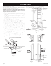
Replacing Fan and Oiling the Motor
The fan motor should be cleaned and oiled once each heating season.
To reach the motor, withdraw the metal shroud surrounding the fan
blade by removing the screws on each side. Oil holes are located on
the top at each end of the motor. Use a few drops of #10 motor oil.
To clean the motor, blow air through its ventilation openings with a
vacuum cleaner or low pressure air source.
If fan motor is replaced, the silicone rubber gaskets, see page 14, Index
No. 5, Part No. 712059 should also be replaced. The gaskets must be
stretched to fit the motor bolts into the gasket holes and then the motor
and gaskets installed on the motor mounting bars.
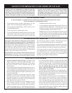
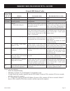
Checking Manifold Pressure
Both Propane and Natural gas valves have a built-in pressure regulator
in the gas valve. Natural gas models will have a manifold pressure
of approximately 3.5” w.c. (.871kPa) at the valve outlet with the inlet
pressure to the valve from a minimum of 5.0” w.c. (1.24kPa) for the
purpose of input adjustment to a maximum of 10.5” w.c. (2.615kPa)
Propane gas models will have a manifold pressure approximately 10.0”
w.c. (2.49kPa) at the valve outlet with the inlet pressure to the valve
from a minimum of 11.0” w.c. (2.739kPa) for the purpose of input
adjustment to a maximum of 13.0” w.c. (3.237kPa).
A 1/8” (3mm) N.P.T. plugged tapping, accessible for test gauge
connection, is located on the outlet side of the gas control.
The built-in regulator comes on at approximately 1/4th pressure and
full on in 10 seconds.
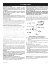
Figure 5
High Altitudes
For altitudes/elevations above 2,000 feet (610m), input ratings should
be reduced at the rate of 4 percent for each 1,000 feet (305m) above
sea level. Canadian High Altitudes for locations having an elevation
above mean sea level between 2,000 feet (610m) and 4,500 feet (1370m),
the manifold pressure is to be decreased from 3.5” w.c. (.871kPa) to
2.8” w.c. (.697kPa) for Natural Gas and from 10.0” w.c. (2.49kPa) to
8.0” w.c. (1.992kPa) for Propane Gas.
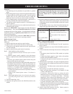
Proper Pilot Flame
The pilot flame (Figure 6) going to the spark must be large enough to
completely cover the sparking area. With the proper flame, only 2 or
3 sparks will occur. More sparks indicate a small pilot flame and no
ignition with spark stopping after approximately 90 seconds generally
means not enough flame.
To adjust pilot flame remove the pilot cover screw on the control valve
(Figure 5), and turn the adjustment screw clockwise to reduce flame.
Replace pilot cover screw to eliminate gas leakage.
The pilot flame will appear large. A blue nearly horizontal flame is
proper. The spark gap must be 1/8” (3mm) . A larger gap can result
in the spark occurring some other place. The pilot flame and the spark
gap are factory checked and tested.
After use, cleaning may be required for the proper flame.
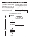
Safety Lockout
S8600H module provides 100 percent shutoff, or safety lockout.
If the pilot fails to light within 90 seconds, the control system
will shut down. The control system must be reset by setting
the thermostat below room temperature for one minute or by
turning off power to the module for one minute.
4”(102mm) NAT
6”(152mm) LP
1 ½”(38mm) NAT
1/4” (6mm) LP
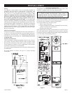
INSTALLATION