


12427-4-0306
Page 10
SERVICE AND MAINTENANCE SUGGESTIONS
CALL SERVICEMAN
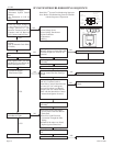
GENERAL: All furnaces have been fire-tested to check for proper op-
eration. This includes, main burner flame, pilot flame, fan operation, fan
control, limit control and automatic valve operation. If the furnace fails to
function on initial installation, it is advisable to re-check the following:
1. 115 volts to the junction box.
2. Inlet gas pressure.
3. The 24 volt system.
4. Type of gas being used and that shown on the rating label.
The Service Department at Empire Comfort Systems, Inc. may be contacted
to assist in servicing furnace.
Standing Pilot Model
Servicing the Pilot and Main Burners, Pilot Orifice, Thermocouple,
and Main Burner Orifices: Disconnect the gas supply at the inlet to the
control valve. Then remove the burner door to gain access to the above
listed components.
Spark Igniter Does Not Light Pilot: With air in the gas line, such as when
the furnace is first installed or was off all summer, the pilot flame may
be too lean to ignite on the first few trials. Turn the control valve knob to
pilot position and depress the red reset button. Holding the button down
continually to bleed the line;.
1. Use lighter rod to light pilot with a match.
2. Use the piezo ignitor at 30 second intervals until it lights.
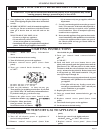
If Electrode Does Not Produce Spark:
1. Check wire connections.
2. Check gap for pilot burner to the electrode tip. Should be between
1/8" (3mm) and 3/16" (5mm). Electrode wire and tip must be more
than 1/4" (6mm) away from all other metal components.
If Pilot Does Not Light By Any Means:
1. Check valve knob for being in the "Pilot" position.
2. Check pilot adjustment for being full open (counterclockwise to
open).
3. If gas is available in the supply tubing, the pilot orifice and/or pilot
burner is probably restricted by a spider web. Clean pilot assembly
and relight.
If Pilot Does Not Remain On After Releasing Knob:
1. Follow instructions and hold button down longer and harder.
2. Determine if pilot flame extends past thermocouple; if not, adjust
input or clean pilot burner.
3. Replace thermocouple if millivolts read less than 15 millivolts.
Main Gas Valve Does Not Open When Thermostat Is Turned To On:
1. Check for 24 volts to valve by removing one wire and touching to the
SAME TERMINAL it was on. Terminal should have a light spark.
DO NOT SHORT ACROSS TERMINALS, AS IT WILL BURN
OUT THE WALL THERMOSTAT.
2. Thermostat wires at the wall may be shorted, so check for a faulty
thermostat.
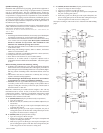
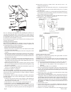
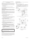
3. To check for line voltage to furnace, remove front panel and short
across two-terminal fan control to allow fan to operate (Figure 14).
CAUTION: Label all wires prior to disconnection when servicing
controls. Wiring errors can cause improper and dangerous operation.
Verify proper operation after servicing.
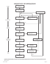
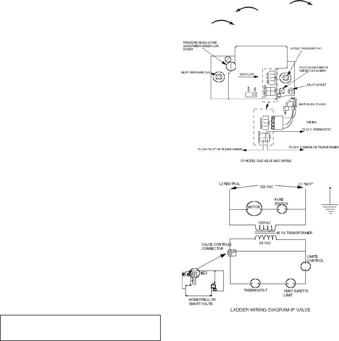
IP-Model Pilot
This heater is using a Honeywell "Smart Valve" system for intermittent
pilot ignition.
On a call for heat by the thermostat this control turns on a 24 volt mini
hot surface ignitor which lights a pilot that in turn lights the main burner.
The gas valve used in this system is a step opening which opens at a
lower pressure for ignition and then steps to a full inlet pressure of 4" H
2
O
pressure on Natural gas and 10" H
2
0 pressure on LP gas.
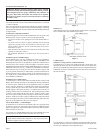
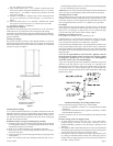
Pilot Flame Adjustment
The pilot flame should envelop 3/8 to 1/2 inch (10 to 13mm) of the tip
of the flame rod. See Figure 10.
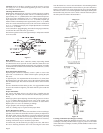
To adjust:
1. Remove the pilot adjustment cover screw.
2. Turn the inner adjustment screw clockwise
to decrease
or counterclockwise
to increase pilot flame. Pilot adjust-
ment is shipped at full flow rate. Turn the inner adjustment screw
clockwise if the inlet pressure is too high.
3. Replace the cover screw after the adjustment to prevent gas leak
-
age.
Figure 15