


13117-9-0907 Page 11
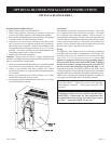
Millivolt wall thermostats are specially designed for use on self-generating systems. They should never be used on line or low voltage
A.C. circuits.
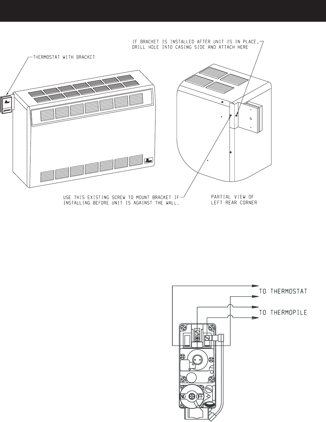
Figure 9
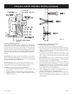
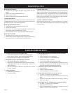
Interior Wall - The thermostat can also be installed on an inside wall
away from the furnace but in the same room.
It is important to use wire of a gauge proper for the length of the wire:
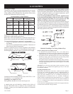
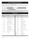
RECOMMENDED WIRE GAUGES
Maximum Length Wire Gauge
1' to 10' 18
10' to 25' 16
25' to 35' 14
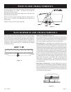
Proper operation depends on a good pilot flame. The flame must cover
the top of the thermopile. Cleaning of the pilot orifice and burner may
be required due to spiders.
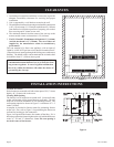
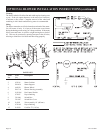
System Check (Figure 10)
A millivolt meter is required to check the system. Millivolt readings
should be:
• Across the thermopile terminals, 400-450 millivolts with
thermostat OFF.
• Across the thermopile terminals, 150 - 250 millivolts with thermostat
ON
• Across the thermostat wires at the valve, less than 30
millivolts with thermostat ON.
• Across the thermostat wires at the thermostat, less than 5
millivolts with thermostat ON. (Strong winds, dirty pilot and low pres
-
sure will reduce readings.)
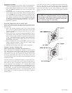
Piezo Pilot Ignitor Instructions
Depressing the button completely causes a spark to occur at the pilot.
This is a substitute for a match which requires opening the pilot hole
cover.
To light the pilot, it is important that the electrode be 1/8" (3mm) from
the thermopile. The spark must occur at the point the burner flame hits
the thermopile. The end of the electrode will be red hot with the pilot
on.
On a new installation with air in the gas line, it is suggested that a match
be used. The match will light the pilot faster than the piezo under this
condition.
Figure 10
THERMOSTAT LOCATION