Rome, New York, USAEnviromaster International LLC
5780 Success Drive, Rome, NY 13440
Phone: 1-800-228-9364
FAX: 1-800-232-9364
Email: emi@enviromaster.com
are selected; fan operation of auto (cycling), high and low (constant), auto fan operation automatically selects fan
speed according to heating or cooling demand; dry mode operates cooling and electric heat simultaneously to
remove humidity, optional electric heat must be selected; test operation allows ease of testing after installation (all
timers are eliminated); non-volatile back-up memory, control settings are maintained for an indefi nite period during
a power outage, when power is restored the equipment will resume operation after a three-minute compressor time
delay; optional hand held infra-red controller. The control voltage between the indoor unit and the outdoor unit shall
be 24 Volts A.C. The 24 Volts shall be generated from the indoor unit’s 24 Volt 40VA transformer.
PART SIX “OUTDOOR UNIT”
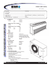
The outdoor unit shall be completely factory assembled, piped and wired. The cabinet shall be fabricated of G60
galvannealed steel, fi nished in “off-white” with corrosion inhibiting polyester powder-coated paint. The unit shall be
furnished with one (1) direct drive, propeller type fan arranged for horizontal discharge. The motor shall have inherent
protection, be of the permanently lubricated type, and resiliently mounted for quiet operation. The fan shall be provided
with a guard to prevent contact with moving parts. The compressor shall be of the high-performance rotary type with
Duratec package which consists of an oversized accumulator, factory installed solid core fi lter drier and thermal
overloads. The compressor shall be mounted so as to avoid the transmission of vibration. The refrigeration system
shall be equipped with a loss of charge switch, and have the capability to operate with a maximum height difference
of 35 feet and overall refrigerant tubing length of 100 feet between indoor and outdoor sections without the need for
line size changes or additional oil. The condenser coil shall be of nonferrous construction with louvered fi ns bonded
to rifl ed copper tubing. The unit shall be controlled by the microprocessor located in the indoor matching unit. The
heating expansion is controlled by a TXV in the outdoor unit. The unit electrical power shall be 208/230 Volts, 1 phase,
60 Hertz. The system shall be capable of satisfactory operation within voltage limits of 208/230 Volts +/- 10%.
PART SEVEN “OPTIONAL EQUIPMENT”
• Hand Held Infrared Remote Controller – used to command the unit-mounted controls.
• 24V Wall Thermostat Control – anti-short cycle compressor protection; fan purge, fan remains on for 60 seconds
after heat/cool call is dropped for improved effi ciency; integral heating relay ensures that the fan operates whenever
electric heat is energized; two stage heating capable when matched up with an EMI heat pump and an appropriate
two stage thermostat.
• 3KW Electric Heat – shall be factory installed; automatic reset high temperature cutout and redundant high
temperature fuse link.
• Single-Stage hydronic heating coil (one row type) w/sweat connections.
• Internal Condensate Pump – shall be fi eld installed or factory installed and shall have 12 ft of head.
• Low Ambient Control – shall consist of a fan cycle switch and a lock-out relay, fi eld installed.
• Hard Start – shall be fi eld installed.
• Sea Coast Style Coated Coils – shall be factory installed; coating shall protect against corrosion due to acids,
solvents and salt.
EMI ENGINEERING SUBMITTAL DFPH093 (FHP12-SHC09)


