


8
Functional Safety Manual
M310/FSM, Rev AA
January 2012
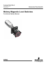
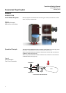
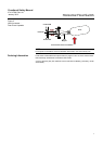
Horizontal Float Switch
DESIGNING A SAFETY
FUNCTION USING THE
LEVEL SWITCH
Safety Function A change in liquid level through the operating range of the float causes the switch to
operate. It may be used in high level or low level safety related applications. In either
case, it is recommended to use the set of contacts (A-A or B-B) which are Open in the
Fail Safe State.
Environmental Limits The designer of the SIF (Safety Instrumented Function) must check that the level
switch is rated for use within the expected environmental limits. See the Mobrey
product data sheet IP101 for environmental limits.
NOTE:
For all product information and documentation downloads, see www.mobrey.com.
Application Limits It is very important that the SIF designer checks for material compatibility by
considering process liquids and on-site chemical contaminants. If the Mobrey level
switch is used outside the application limits or with incompatible materials, the
reliability data and predicted SIL capability becomes invalid.
The construction materials of a Mobrey level switch are specified in the product data
sheet and the product reference manual (see Table 1 on page 5).
Use the model code on the product label and the ordering information table and
specification in these product documents to find out the construction materials.
Design Verification A detailed Failure Modes, Effects and Diagnostics Analysis (FMEDA) report for the
Mobrey magnetic level switch is available to download from the web sites
www.mobrey.com and www.mobrey.com. The FMEDA report details all failure rates
and failure modes as well as expected lifetime.
NOTE:
The FMEDA report is available from the Safety quick link at www.mobrey.com.
In the right-hand panel, there are SIL documents including the FMEDA report.
The achieved Safety Integrity Level (SIL) of an entire Safety Instrumented Function
(SIF) design must be verified by the designer using a PFD
AVG
calculation considering
the architecture, proof test interval, proof test effectiveness, any automatic diagnostics,
average repair time, and the specific failures rates of all equipment included in the SIF.
Each subsystem must be checked to assure compliance with minimum Hardware
Fault Tolerance (HFT) requirements. When using the Mobrey level switch in a
redundant configuration, a common cause factor of at least 5% should be included in
the safety integrity calculations.
The failure rate data listed in the FMEDA report is only valid for the useful lifetime of
the Mobrey level switch. The failure rates increase after this useful lifetime period has
expired. Reliability calculations based on the data listed in the FMEDA report for
mission times beyond the lifetime may yield results that are too optimistic, i.e. the
calculated SIL will not be achieved.