11
TECHNICAL REPTECHNICAL REP
TECHNICAL REPTECHNICAL REP
TECHNICAL REP
AIR GUIDEAIR GUIDE
AIR GUIDEAIR GUIDE
AIR GUIDE
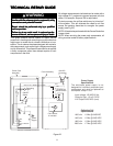
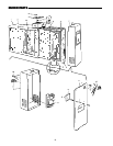
The solid-state power supply is not
designed for individual component part
replacement and must be replaced as
a complete "snap-in" unit.
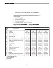
Input voltage: 120 VAC 60 Hz.
Output to light: 1.5 to 2.5 VDC
H.V. Output: 6450 VDC (nom)
Collecting Cell
Specifications
Power Supply
Specifications
1000 cfm - 1.0 Ma @ 6450VDC
1400 cfm - 1.2 Ma @ 6450 VDC
1600 cfm - 1.5 Ma @ 6450 VDC
2000 cfm - 1.7 Ma @ 6450 VDC
Figure 22
WARNING
!
Do not attempt repair of this unit unless you areDo not attempt repair of this unit unless you are
Do not attempt repair of this unit unless you areDo not attempt repair of this unit unless you are
Do not attempt repair of this unit unless you are
familiar with the necessary tools, equipment, utilityfamiliar with the necessary tools, equipment, utility
familiar with the necessary tools, equipment, utilityfamiliar with the necessary tools, equipment, utility
familiar with the necessary tools, equipment, utility
connections and potential hazards.connections and potential hazards.
connections and potential hazards.connections and potential hazards.
connections and potential hazards.
Repair should be performed only by a qualifiedRepair should be performed only by a qualified
Repair should be performed only by a qualifiedRepair should be performed only by a qualified
Repair should be performed only by a qualified
service provider.service provider.
service provider.service provider.
service provider.
Failure to do so could result in reduced perfor-Failure to do so could result in reduced perfor-
Failure to do so could result in reduced perfor-Failure to do so could result in reduced perfor-
Failure to do so could result in reduced perfor-
mance of the unit, serious personal injury or death.mance of the unit, serious personal injury or death.
mance of the unit, serious personal injury or death.mance of the unit, serious personal injury or death.
mance of the unit, serious personal injury or death.
This guide contains service checks to assist service
personnel in locating and correcting any malfunction that
might occur to render the air cleaner ineffective or inop-
erative. The air cleaner has been designed with replace-
able components, such as the high-voltage power supply
and air flow switch. This allows the serviceman to replace
a faulty component rather than attempt repairs of such
components in the field.
All voltage measurements indicated can be made with a
high voltage D.C. probe and a general purpose volt ohm
meter. For example: Simpson 260 or equivalent.
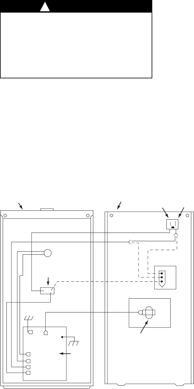
For test purposes, the air flow switch may be “wired out”
of the system. This will eliminate the need for air flow
across the sensing thermistor to energize the power
supply (see Fig 23).
NOTE: All tests to be performed with the Ozone Reduction
Jumper intact.
NOTE: When servicing the power pack components, all
wiring must be routed to factory specifications.
120 VAC
Connector
L1 L2
Operating
Light
ON/OFF
Switch
Power Pack
Assembly
Cover Assembly
(If Required)
Airflow Switch
Cell Contact
& Insulator
Power
Supply
Gnd
Red
Blk
Wht
Wht
Blk
Wht/Brn
Wht
Blk
Blu
Wht
Blu
Wht or Wht/Brn*
Blk
*Wht from L2 or Wht/Brn from Air Flow
Wht from L2 or Wht/Brn from Air Flow


