


Installation on Emerson Fans with
a Center Screw and with Modular
(Detachable) Switch Cups
1.Remove all parts and parts packages
from the carton.
5.Carefully locate the white and blue
wires (labeled either "L" or "LIGHT") in
the switch cup and remove the wire
connectors from the wires.
6.Insert the black and white wires from
the light fitter(7) through the center hole
in the switch cup (Figure 2) and thread
the switch cup onto the light fitter. Hold
wires taut while installing switch cup to
prevent the wires from twisting.
Securely tighten the fitter to the switch
cup.
7.Insert the black and white wires through
the lockwasher(7) and hex nut(8)
supplied. Firmly tighten the hex nut to
secure the light kit fitter to the switch
cup.
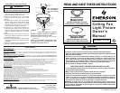
8.Connect the white wire from the switch
cup to the white wire of the light fitter
(Figure 2). Connect the blue wire from
the switch cup to the black wire of the
light fitter. Use listed wire connectors
(previously removed in step 5) to make
connections (Figures 2 and 3).
9. Carefully tuck all wires and splices
into the switch cup(1). (Figure 2.)
10.Connect the motor connector(4) to the
switch cup connector(5).
11.Position the cup/light fitter(1)(7) on the
cover plate(2) and install the three
screws(3) that were previously removed
in step 2 and tighten securely.
Assembly and Installation
NOTE: For installation on Emerson
fans with a center screw in modular
(detachable) switch cup, proceed to
step 1, page 2. For fans with center
screw in switch housing cover,
proceed to step 1, page 3.
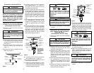
4.Remove the center screw(6) from the
switch cup (Figure 1).
12.Proceed to “Installation of Glass Bowl”
section.
Installation on Emerson Fans
With Center Screw in Switch
Housing Cover
(Not Modular Switch Cup)
1.Remove all parts and parts packages
from carton.
2.Remove the cover from fan switch
housing(1) by removing the two outer
screws(2). (See Figure 4).
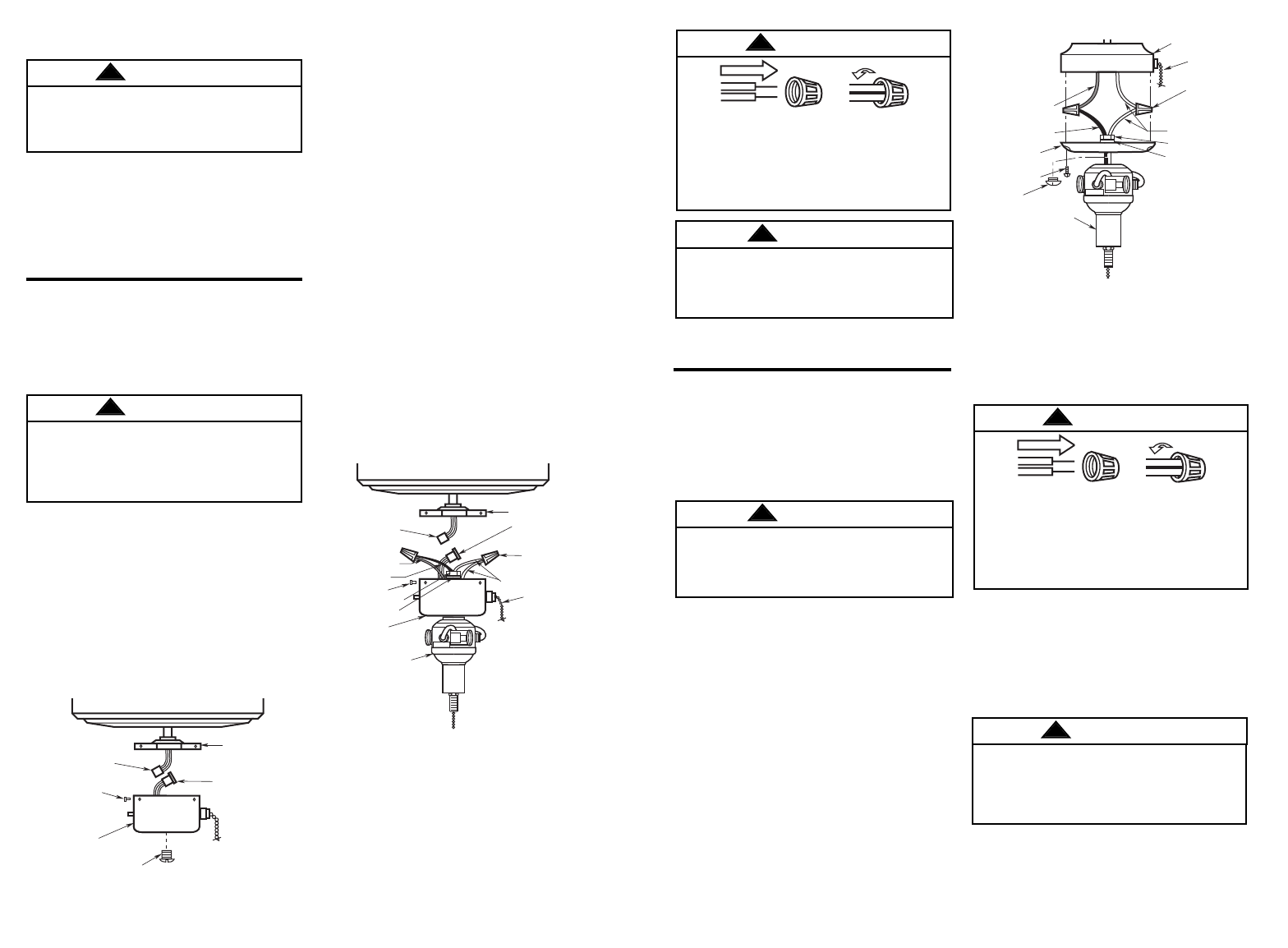
3.Remove the center screw(4) in the
switch housing cover(5). Insert the
black and white wires from the light kit
fitter(6) thru the hole and thread the
switch housing cover tightly onto the
light kit fitter.
4.Insert the black and white wires through
the lockwasher(7) and hex nut(8)
supplied. Firmly tighten the hex nut to
secure the light kit fitter to the switch
cup.
5.Carefully pull down the white and blue
wires from the switch housing(1) and
remove the wire connectors.
Do not install or use the fixture if any
part is missing or damaged. Contact
your dealer for replacement.
To avoid possible electrical shock,
be sure electricity is turned off at the
main fuse or circuit breaker box
before wiring.
(3) SCREWS
(5) SWITCH CUP
CONNECTOR
(2) COVER PLATE
(6) WIRE
CONNECTORS
WHITE WIRES
(1) SWITCH
CUP
BLACK WIRE
FAN SWITCH
CHAIN
(8) LOCKWASHER
(9) HEX NUT
(7) LIGHT
FITTER
BLUE WIRE
(4) MOTOR
CONNECTOR
(3) WIRE
CONNECTORS
WHITE WIRES
BLUE WIRE
BLACK WIRE
FAN SWITCH
CHAIN
(1) SWITCH HOUSING
ASSEMBLY
(5) COVER
(2) SCREWS
(4) CENTER
SCREW
(6) LIGHT FITTER
(7) LOCKWASHER
(8) HEX NUT
2 3
Figure 4
Figure 2
(3) SCREWS
(6) CENTER SCREW
(1) SWITCH
CUP
(4) MOTOR
CONNECTOR
(2) COVER PLATE
(5) SWITCH CUP
CONNECTOR
Figure 1
NOTE: YOUR FITTER
MAY NOT LOOK THE
SAME AS THE ONE IN
THIS ILLUSTRATION.
HOWEVER, IT
INSTALLS IN A
SIMILAR MANNER.
Figure 3
To avoid possible fire or electrical
shock, make certain no bare wire
strands are exposed outside wire
connectors.
WARNING
!
WARNING
!
WARNING
!
To avoid possible fire or electric shock,
be careful not to pinch wires between
switch cup and the cover plate.
WARNING
!
To avoid possible electric shock, be
sure electricity is turned off at the main
fuse or circuit breaker box before wiring.
WARNING
!
2.Remove the switch cup(1) from the
cover plate(2) by removing the three
screws(3) around the side of the switch
cup (Figure 1).
3.Disconnect the motor connector(4)
from the switch cup connector(5)
(Figure 1).
6.Connect the white wire from the ceiling
fan to the white wire of the light kit
fitter(6). Connect the blue wire from the
ceiling fan to the black wire of the light
kit fitter. Use listed wire connectors(3)
(previously removed in step 3) to make
connections. (Figures 4 and 5.)
7.Carefully tuck all wires and splices into
the switch housing(1).
8.Attach the cover/light fitter(5)(6) to the
switch assembly housing(1) using the
two screws(2) that were removed in
Step 2) (Figure 4.)
9.Proceed to “Installation of Glass Bowl”
section.
To avoid fire or electrical shock, be
careful not to pinch wires between
the switch housing assembly and
the cover.
WARNING
!
Figure 5
To avoid possible fire or electrical
shock, make certain no bare wire
strands are exposed outside wire
connectors.
WARNING
!