


7.Insert the black and white wires through
the lockwasher (8) and hex nut (9)
(supplied). Firmly tighten the hex nut to
secure the light fitter to the switch cup.
8.Connect the white wire from the switch
cup to the white wire of the light fitter
(Figure 2). Connect the blue wire from
the switch cup to the black wire of the
light fitter. Use listed wire connectors
(previously removed in step 5) to make
connections (Figures 2 and 3).
9. Carefully tuck all wires and splices
into the switch cup (1). (Figure 2.)
10. Connect the motor connector (4) to
the switch cup connector (5).
Assembly and Installation
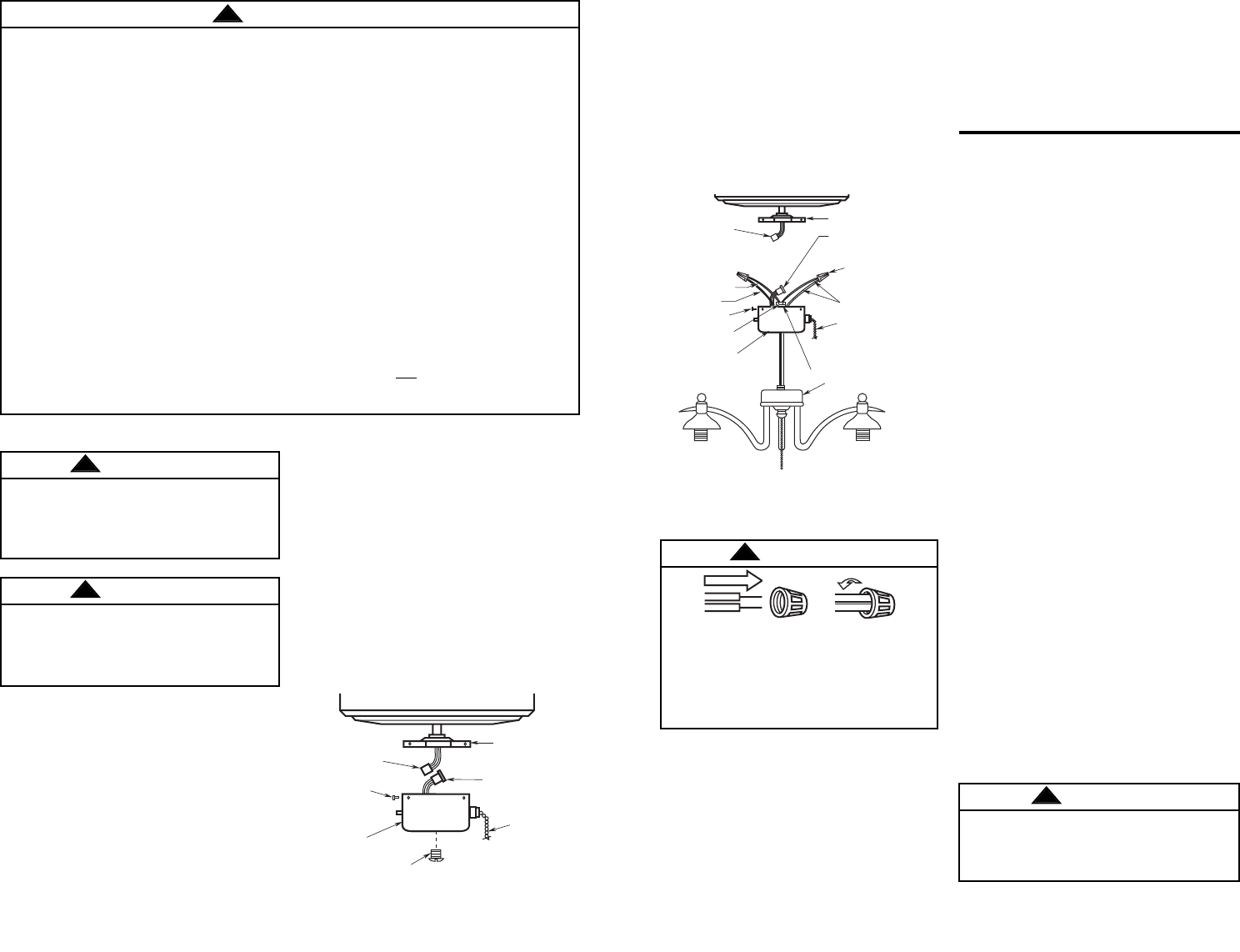
4.Remove the center screw (6) from the
switch cup (Figure 1).
5.Carefully locate the white and blue
wires (labeled either "L" or "LIGHT") in
the switch cup and remove the wire
connectors from the wires.
6.Insert the black and white wires from
the light fitter (7) through the center
hole in the switch cup (Figure 2) and
thread the switch cup onto the light
fitter. Hold wires taut while installing
switch cup to prevent the wires from
twisting.
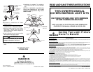
11. Position the cup/light fitter (1)(7) on the
cover plate (2) and install the three
screws (3) that were previously
removed in step 2 and tighten
securely.
12. Proceed to “Installation of “Glass
Shades” section.
Installation on Emerson Fans
Having Two-Piece Die-Cast
Switch Housings
1.Remove all parts and parts packages
from carton.
2.Remove the cover (5) from the switch
housing (1) by removing the two outer
screws (2). (See Figure 4.)
3.Remove the center screw (4) from the
cover (5). Insert the black and white
wires from the light kit fitter (6) through
the hole and thread the switch housing
cover tightly onto the light kit fitter.
4.Insert the black and white wires through
the lockwasher (8) and hex nut (7)
supplied. Firmly tighten the hex nut to
secure the light kit fitter to the switch
housing cover (5).
5.Carefully locate the white and blue
wires (labeled either “L” or “LIGHT”) in
the switch housing and remove the
wire connectors (3) from the wires.
6.Connect the white wire from the ceiling
fan to the white wire of the light fitter
(6). Connect the blue wire from the
ceiling fan to the black wire of the light
fitter. Use listed wire connectors
(previously removed in step 3) to make
connections. (Figures 3 and 4.)
7.Carefully tuck all wires and splices into
the switch housing (1).
8.Attach the cover/light fitter (5) (6) to the
switch assembly housing (1) using the
two screws (2) that were removed in
Step 2) (Figure 4.)
(9) HEX NUT
(1) SWITCH CUP
(8) LOCKWASHER
(7) LIGHT FITTER
(5) SWITCH CUP
CONNECTOR
(6) WIRE
CONNECTORS
(4) MOTOR
CONNECTOR
BLACK WIRE
(3) SCREWS
FAN SWITCH
CHAIN
WHITE WIRES
(2) COVER PLATE
BLUE WIRE
2 3
Figure 2
(3) SCREWS
(6) CENTER SCREW
(1) SWITCH
CUP
(4) MOTOR
CONNECTOR
(2) COVER PLATE
(5) SWITCH CUP
CONNECTOR
FAN SWITCH
CHAIN
Figure 1
Installation on Emerson Fans
Having Modular Switch Cup with
Center Screw
1.Remove all parts and parts packages
from the carton.
2.Remove the switch cup (1) from the
cover plate (2) by removing the three
screws (3) around the side of the switch
cup (Figure 1).
3.Disconnect the motor connector (4)
from the switch cup connector (5)
(Figure 1).
Safety Instructions
To avoid fire, shock, and serious personal injury, follow all instructions carefully.
1. Read your Owner's Manual carefully before installing the light fixture. Retain Owner's
Manual for future reference.
2. Be careful of the fan and blades when cleaning, painting, or working near the fan.
Before installing or servicing the light fixture or ceiling fan, switch power off at
service panel and lock service panel disconnecting means to prevent power from
being switched on accidentally. When the service disconnecting means cannot be
locked, securely fasten a warning device, such as a tag, to the service panel.
3. Do not exceed the wattage indicated on fixture.
ADDITIONAL SAFETY INSTRUCTIONS FOR INSTALLATION
1. To avoid possible electrical shock be sure electricity is turned off at the main fuse or
circuit breaker box before wiring.
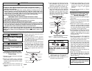
2. Make certain no bare wires are exposed outside the wire connectors.
3. All wiring must conform to national and local electrical codes.
4. Follow the recommended instructions for the proper method of wiring your new light
fixture. If you feel you do not have enough electrical wiring knowledge or experience,
have your light fixture installed by a licensed electrician. Any electrical work not
described in this manual should be performed by a licensed electrician.
WARNING: To reduce the risk of possible fire and electrical shock, install only on
Emerson “CF” and “F” Series Ceiling Fans. This light kit is not to be used with CF652,
CF653, CF670, CF680, CF742 and CF2000 Series Ceiling Fans installed in damp or wet
locations.
WARNING
!
Do not install or use the light fixture
if any part is missing or damaged.
Call toll-free:
1-800-654-3545
To avoid possible electrical shock,
be sure electricity is turned off at the
main fuse or circuit breaker box
before wiring.
WARNING
!
WARNING
!
Figure 3
To avoid possible fire or electrical
shock, make certain no bare wire
strands are exposed outside wire
connectors.
WARNING
!
To avoid possible fire or electric shock,
be careful not to pinch wires between
switch housing and light fitter.
WARNING
!
NOTE: YOUR FITTER MAY NOT LOOK THE SAME AS
THE ONE IN THIS ILLUSTRATION.
HOWEVER, IT INSTALLS IN A SIMILAR MANNER.