


3
Do not install or use fan if any part is damaged or
missing. Call Toll-Free:
1-800-654-3545
This product is designed to use only those parts
supplied with this product and/or any accessories
designated specifically for use with this product by
Emerson Company. Substitution of parts or
accessories not designated for use with this product
by Emerson Company could result in personal injury
or property damage.
WARNING
!
WARNING
!
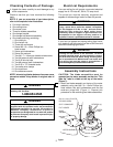
Checking Contents of Package
1. Unpack the items carefully to avoid damage to any
of the components.
Check to see that you have received the following
parts:
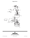
NOTE: If you are uncertain of part description,
refer to the exploded view illustration.
a. Fan motor assembly
b. One ceiling cover
c. One motor cover
d. Three fan blades assemblies
e. One hanger bracket
f. One hanger ball/downrod assembly
g. One loose parts bag, containing:
1. One clevis pin
2. One hairpin clip
3. Three wire connectors
4. Seven M6-1.0 x 12mm Phillips hex
head screws
5. Seven split lockwashers
6. Seven flat washers
7. Two M4 -.7 x 10mm pan head knurled screws
8. Two M4 external tooth lockwashers
9. Two 8-32 knurled nuts
10. Two #8 external tooth lockwashers
11. Two 8-32 x .75” threaded studs
12. Two safety wire clamps
13. One eye screw
14. One setscrew wrench
NOTE: Intermixing blades between fans can cause
excessive wobble. Keep blades in original sets of
three.
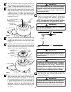
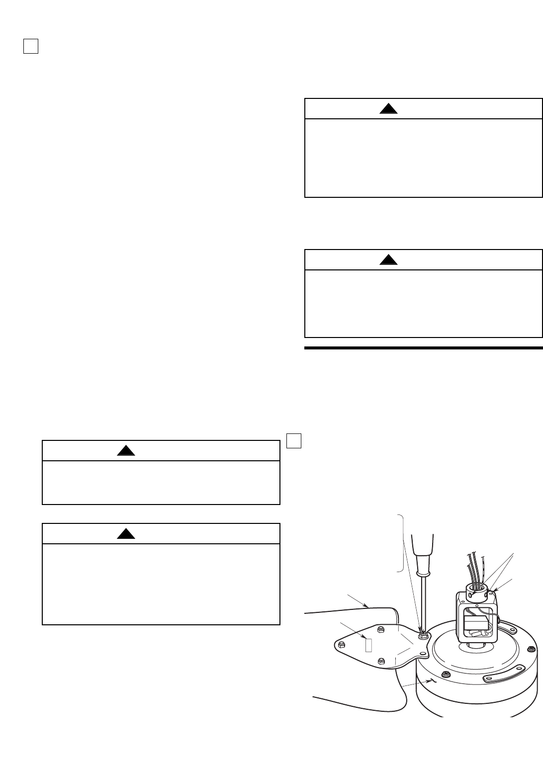
Assembly Instructions
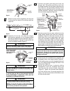
CAUTION: The blade assemblies must be
mounted on the motor assembly so that the “This
Side Up” label is visible at the top of the motor
(Figure 1).
1. Install one blade assembly on the top of the motor
assembly using two M6-1.0 x 12mm Phillips hex
head screws, two split lockwashers and two flat
washers (supplied) (Figure 1). Repeat this
procedure for the remaining two blade assemblies.
Electrical Requirements
If your fan is to replace an existing ceiling light fixture,
turn electricity off at the main fuse box at this time and
remove the existing light fixture.
Your new ceiling fan will require a grounded electrical
supply line of 120 volts AC, 60 Hz, 15 amp circuit.
The outlet box must be securely anchored and
capable of withstanding a load of at least 50 pounds.
To reduce the risk of fire, electric shock, or personal
injury, mount fan to outlet box marked “Acceptable
for Fan Support of 50 lbs. or less”, and use screws
supplied with outlet box. Most outlet boxes
commonly used for support of light fixtures are not
acceptable for fan support and may need to be
replaced. Consult a qualified electrician if in doubt.
WARNING
!
Turning off wall switch is not sufficient. To avoid
possible electrical shock, be sure electricity is turned
off at the main fuse box before wiring. All wiring must
be in accordance with National and Local codes and
the ceiling fan must be properly grounded as a
precaution against possible electrical shock.
WARNING
!
Figure 1
LABEL
MOTOR ASSEMBLY
BLADE
ASSEMBLY
M6-1.0 x 12mm PHILLIPS
HEX HEAD SCREW
SPLIT LOCKWASHER
FLAT WASHER
SETSCREW (2)
MOTOR
YOKE