


Sensor Installation: F-Series 11
Determining a Location
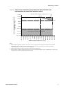
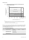
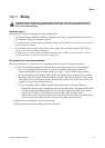
Maximum wiring distances
If the transmitter is mounted remotely from the sensor, the maximum distance between the sensor and
transmitter depends on cable type. See Table 2.
For high-temperature and extreme high-temperature F-Series sensors, note the following:
• For sensors with a Model 1700/2700 transmitter, the transmitter is considered to be integrally mounted
on the sensor, so Table 2 does not apply.
• For sensors with a junction box or core processor, the limits in Table 2 apply only to the wiring
between the junction box or core processor and a remotely mounted transmitter. The length of the
flexible conduit on which the junction box or core processor is mounted does not need to be
considered.
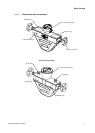
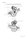
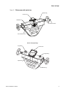
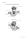
Pipe run
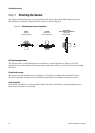
Micro Motion sensors do not require a straight run of pipe upstream or downstream.
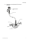
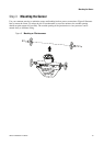
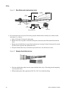
Valves
After the sensor and transmitter have been installed, you must perform the zeroing procedure. During the
zeroing procedure, flow through the sensor must be halted and the sensor tubes must be completely full of
process fluid. A shutoff valve, downstream from the sensor, is recommended to halt flow during the zeroing
procedure. For more information about zeroing, refer to the instruction manual shipped with the transmitter.
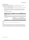
Table 2 Maximum cable lengths
Cable type Wire size Maximum length
Micro Motion 9-wire to an MVD
transmitter or core processor
Not applicable 60 feet (20 meters)
Micro Motion 9-wire to all other
transmitters
Not applicable 1000 feet (300 meters)
Micro Motion 4-wire Not applicable 1000 feet (300 meters)
User-supplied 4-wire
Power wires (VDC) 22 AWG (0,35 mm
2
) 300 feet (90 meters)
20 AWG (0,5 mm
2
) 500 feet (150 meters)
18 AWG (0,8 mm
2
) 1000 feet (300 meters)
Signal wires (RS-485) 22 AWG (0,35 mm
2
) or larger 1000 feet (300 meters)