IMPORTANT
This Owner’s Manual is divided into two sections.
The first section, REMOTE CONTROL
PROCEDURES, describes how to install the 9-volt
alkaline battery (not included) in the remote
control transmitter, and how to set the operating
frequency of the transmitter and receiver. These
instructions must be performed prior to
installation of the ceiling fan as described in the
second section, CEILING FAN PROCEDURES.
REMOTE CONTROL
PROCEDURES
General
The remote control supplied with your Emerson
ceiling fan consists of a hand-held transmitter and a
receiver which is mounted in the switch housing. The
remote control is designed to separately control your
ceiling fan and light intensities. There are four push
buttons (HI, MED, LOW, OFF) to set the fan speed
and turn the fan off. The REV push button changes
the airflow direction of the fan blades. The U/L
(uplight) and D/L (downlight) pushbuttons turn the
lights on and off and control the light intensities. The
red indicator light will illuminate while any button is
pressed, indicating that the battery is good.
The remote control transmitter is powered by a 9-volt
alkaline battery (not included). To prevent possible
damage if the battery should leak, be sure to remove
the battery when the control is not to be used for an
extended period of time.
Code switches in the transmitter and receiver may be
set in 16 different positions. If your fan and light go on
and off without using your control, you may be getting
interference from other remote units such as garage
door openers, car alarms or security systems. To
remedy this situation, simply change the combination
code in your transmitter and receiver.
Preset Memory Feature
Your Emerson remote control receiver is equipped
with a preset memory feature. If the electrical supply
to the receiver is controlled through a wall switch,
when the switch is turned off, the control will
remember the light intensities and fan speed. When
the switch is turned back on, the lights and fan will
resume operation as they were prior to the switch
being turned off.
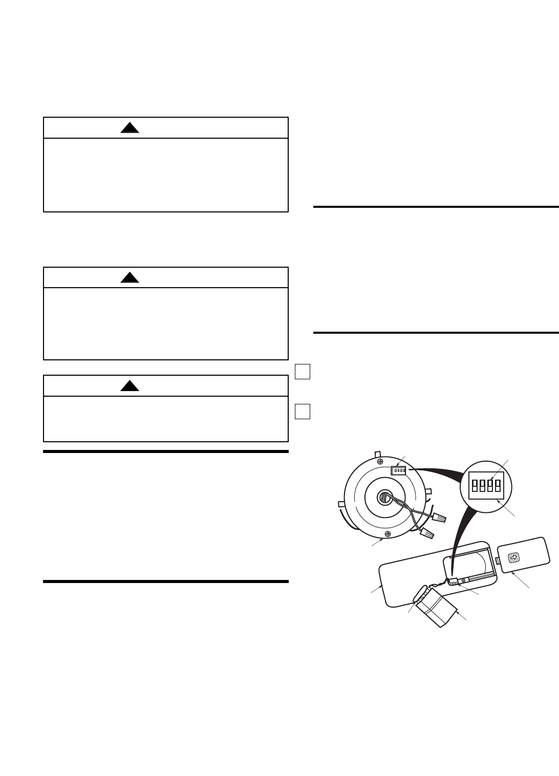
Installation of Battery
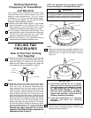
1. Remove the battery cover by pressing firmly below
the arrow and sliding the cover off the control
(Figure 1).
2. Remove the connector from the battery
compartment and attach it to the 9-volt alkaline
battery (not included).
4
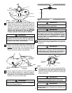
Electrical Requirements
If your fan is to replace an existing ceiling light fixture,
turn electricity off at the main fuse box at this time and
remove the existing light fixture.
Your new ceiling fan will require a grounded electrical
supply line of 120 volts AC, 60 Hz, 15 amp circuit.
The outlet box must be securely anchored and capa-
ble of withstanding a load of at least 50 pounds.
To reduce the risk of fire, electric shock, or personal
injury, mount fan to outlet box marked acceptable for
fan support, and use screws supplied with outlet
box. Most outlet boxes commonly used for support
of light fixtures are not acceptable for fan support
and may need to be replaced. Consult a qualified
electrician if in doubt.
To avoid fire or shock, follow all wiring instructions
carefully. Any electrical work not described in these
instructions should be done or approved by a
licensed electrician.
Turning off wall switch is not sufficient. To avoid
possible electrical shock, be sure electricity is
turned off at the main fuse box before wiring. All
wiring must be in accordance with National and
Local codes and the ceiling fan must be properly
grounded as a precaution against possible electrical
shock.
WARNING
!
WARNING
!
WARNING
!
CODE
SWITCH
BATTERY
COVER
BATTERY
BATTERY
CONNECTOR
REMOTE CONTROL
TRANSMITTER
REMOTE CONTROL
RECEIVER
CODE SWITCH
SWITCH
LEVERS
CODE
SWITCH
1 2 3 4
1 2 3 4
ON
ON
Figure 1


