


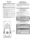
Setting Operating
Frequency of Transmitter
and Receiver
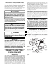
Your remote control transmitter and receiver have
code switches which must be set on one of 16
possible code combinations. The four levers
(numbered 1, 2, 3, and 4) on the switches are factory-
set in the ON (up) position. Do not use this setting.
Change the switch settings as follows:
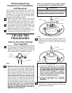
1. Slide the four switch levers (Figure 1) in the remote
control transmitter to your choice of ON (up) or
down positions. Use a ball-point pen or small
screwdriver and slide the levers firmly up or down.
2. In the receiver, slide the four switch levers in the
same positions as set in the transmitter. Make sure
the levers on both switches are in the same
positions; otherwise the fan will not operate.
3. Position the battery in the transmitter battery
compartment and replace the battery cover.
CEILING FAN
PROCEDURES
How to Put Your Ceiling
Fan Together
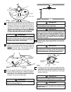
1. Remove the hanger ball by loosening the setscrew
in the hanger ball until the ball falls freely down the
downrod (Figure 2). Remove the pin from the
downrod, then remove the hanger ball. Retain the
pin and hanger ball for reinstallation in Step 5.
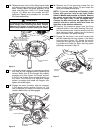
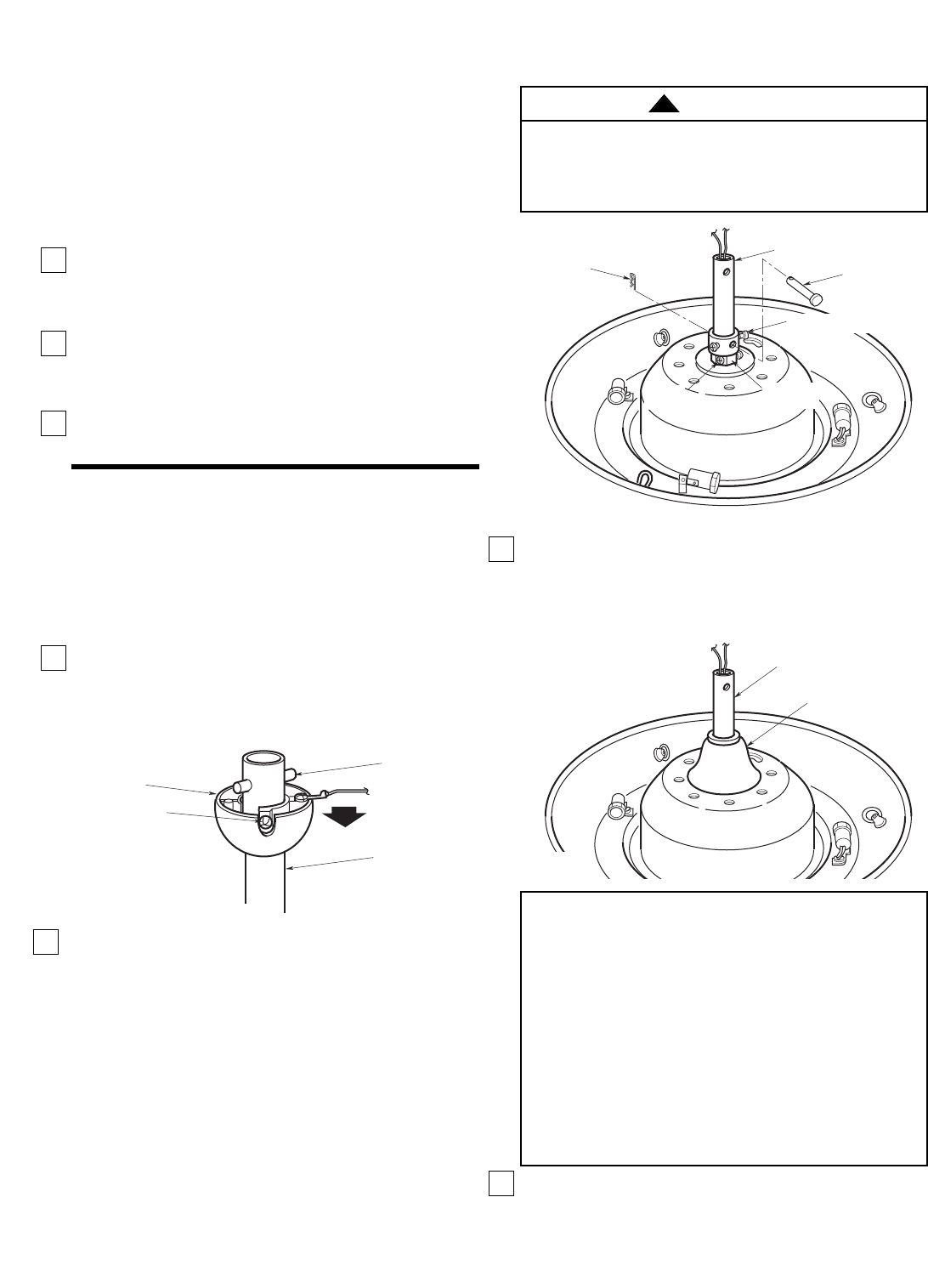
2. Separate, untwist and unkink the two 80” motor
leads. Route the motor lead wires through either
the 4-1/2” or the 18” downrod. Remove the two
upper setscrews from the motor coupling. Align the
clevis pin holes in the downrod with the holes in the
motor coupling. Install the clevis pin and secure
with the hairpin clip (Figure 3). The clevis pin must
go through the holes in the motor coupling and the
holes in the downrod. Be sure to push the straight
leg of the hairpin clip through the hole near the end
of the clevis pin until the curved portion of the
hairpin clip snaps around the clevis pin. The hairpin
clip must be properly installed to prevent the clevis
pin from working loose. Pull on the downrod to
make sure the clevis pin is properly installed.
Reinstall the upper setscrews in the motor
coupling. Check that the lower setscrews are
tightened securely (Figure 3).
NOTE: The setscrews must be properly installed
as described above, or fan wobble could result.
4. Position the ceiling cover over the downrod. Be
sure the cover is oriented correctly, with the large
opening at the top (Figure 5).
5
DOWNROD
PIN
SETSCREW
HANGER
BALL
Figure 2
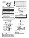
3. Make sure the grommet is properly installed in the
coupling cover, then slide the coupling cover on the
downrod until it rests on the motor housing
(Figure 4).
It is critical that the clevis pin in the motor coupling
is properly installed and the setscrews securely
tightened. Failure to verify that the pin and setscrews
are properly installed could result in the fan falling.
WARNING
!
MOTOR
COUPLING
UPPER SETSCREW (2)
CLEVIS PIN
DOWNROD
HAIRPIN
CLIP
LOWER
SETSCREW (2)
Figure 3
DOWNROD
COUPLING COVER
Figure 4
IMPORTANT
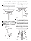
A. If you have installed an 18” or longer
downrod and are planning to install the
decorative support rods assembly, proceed
to “INSTALLATION OF DECORATIVE
SUPPORT RODS ASSEMBLY” on page 9.
After you have installed the decorative
support rods assembly, continue with the
following installation procedures.
B. If you have installed the 4-1/2” downrod,
continue now with the following
procedures.