


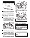
8. Turn the fan motor assembly upside down in
preparation for mounting the fan blade assemblies.
Remove and discard three shipping retainers
securing the motor hub in the motor housing.
NOTE: Take care not to scratch fan housing when
installing blades.
9. Loosely attach one blade assembly to the motor
hub using two 1/4-20 x 1/2” Phillips oval head
flange screws (Figure 6). Make sure the screws are
NOT tightened. Repeat this procedure for the other
four blade assemblies.
10. The blade flanges have an interlocking feature
that must be fully engaged before tightening the
screws. Make sure all the flanges are properly
engaged and then tighten the flange screws. If
one of the flanges does not seat properly on the
motor hub, loosen the adjacent flange screws, re-
engage and reseat the flanges, then tighten the
screws again.
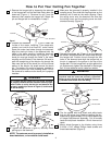
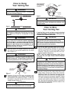
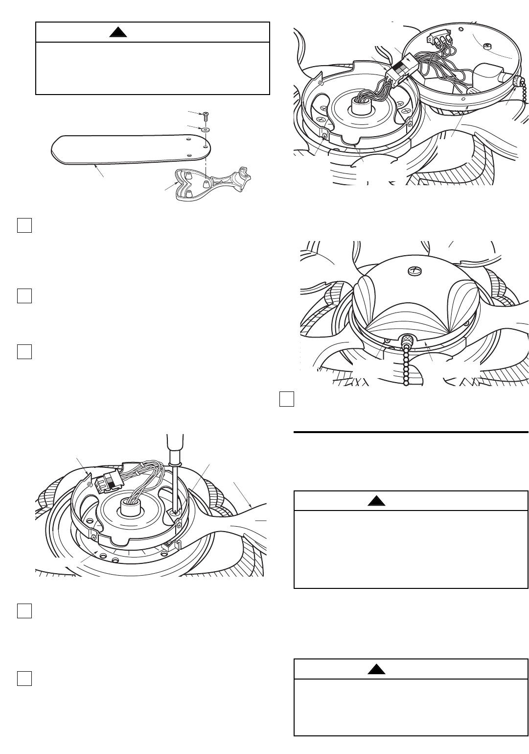
11. Engage the connector of the switch housing
assembly with the motor connector (Figure 7).
The two connectors are keyed and color-coded
and must be mated correctly (color-to-color)
before they can be engaged. Make sure the
connector latch closes properly.
12. Remove the four mounting screws from the switch
housing plate (Figure 7). Position the switch hous-
ing assembly on the switch housing plate and
secure using the four mounting screws (Figure 8).
NOTE: Do not pinch wires between the switch
housing assembly and the switch housing plate.
5
MOUNTING
SCREWS (4)
SLOT FOR PULL
CHAIN SWITCH
LATCH
PULL
CHAIN
SWITCH
MOTOR
CONNECTOR
SWITCH
HOUSING
CONNECTOR
SWITCH
HOUSING
ASSEMBLY
Figure 7
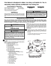
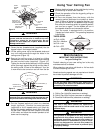
FAN BLADE
BLADE FLANGE
3/16-24 x 5/16" SLOTTED PHILLIPS
HEAD SCREW (3)
BLADE WASHER (3)
Figure 5
BLADE FLANGE
1/4-20 x 1/2" PHILLIPS
HEAD FLANGE SCREWS
(INSTALLED THROUGH SLOT
IN SWITCH HOUSING PLATE)
SWITCH HOUSING
PLATE
MOTOR HUB
Figure 6
MOUNTING
SCREWS (4)
SWITCH HOUSING
ASSEMBLY
Figure 8
Electrical Requirements
The outlet box must be securely anchored and capa-
ble of withstanding a load of at least 50 pounds.
If your fan is to replace an existing ceiling light fixture,
turn electricity off at the main fuse box at this time and
remove the existing light fixture.
Your new ceiling fan will require a grounded electrical
supply line of 120 volts AC, 60 Hz, 15 amp circuit.
To reduce the risk of personal injury, do not bend the
blade flange when installing the blade flanges,
balancing the blades or cleaning the fan. Do not
insert foreign objects in between rotating fan blades.
WARNING
!
To reduce the risk of fire, electric shock, or personal
injury, mount fan to outlet box marked “Acceptable
for Fan Support”, and use screws supplied with out-
let box. Most outlet boxes commonly used for
support of light fixtures are not acceptable for fan
support and may need to be replaced. Consult a
qualified electrician if in doubt.
WARNING
!
To avoid fire or shock, follow all wiring instructions
carefully.
Any electrical work not described in these
instructions should be done or approved by a
licensed electrician.
WARNING
!
13. You have now completed the assembly of your
new ceiling fan. You can now proceed with
hanging and wiring your fan.
NOTE: The switch housing assembly must be
oriented so that the pull chain switch will fit into
the rounded slot (Figure 7) in the switch housing
plate.