


10
U.L. Model No.: CF905
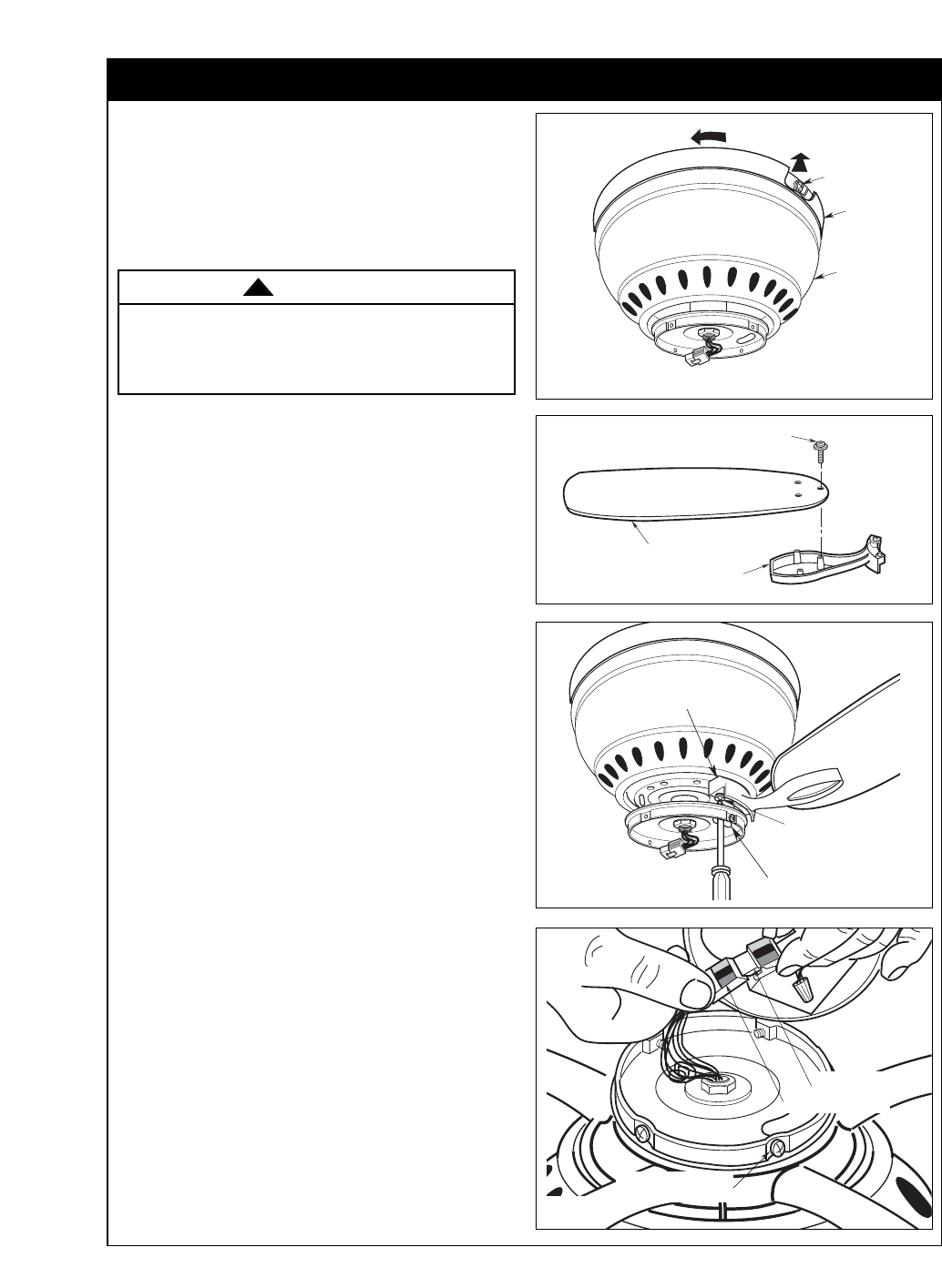
How to Put Your Ceiling Fan Together (continued)
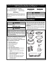
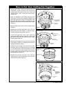
CEILING
TRIM RING
FAN
HOUSING
COVER
MOUNTING
SCREW HEADS
Figure 9
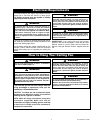
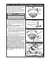
FAN BLADE
10-24 x 5/16" WASHER
HEAD BLADE SCREW (3)
BLADE FLANGE
Figure 10
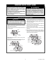
9. Push the trim ring upwards and rotate so that it
engages and locks onto the four mounting screw
heads of the fan housing cover (Figure 9).
10. Mount the blade flanges to the fan blades using
three 10-24 x 5/16” washer head blade screws
per blade (supplied) (Figure 10). Repeat for the
four remaining blades.
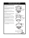
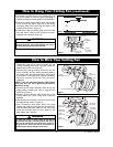
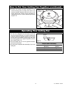
11. Attach one blade assembly to the motor using the
two 1/4-20 x 9/16” captive flange screws with
lockwashers provided for each flange (Figure 11).
Make sure the screws are tightened securely.
Repeat this procedure for the other four blade
assemblies.
NOTE: Take care not to scratch the fan housing
when installing the blade assemblies.
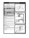
12. Engage the connector of the switch housing
assembly with the fan motor assembly connector
(Figure 12). The two connectors are keyed and
color-coded and must be mated correctly (color-to
color) before they can be engaged. Make sure the
connector latch closes properly.
13. Remove the four switch housing assembly
mounting screws from the switch housing plate
and retain for future use (Figure 12).
NOTE: To install an accessory light kit, remove
switch housing and make light kit electrical
connections to blue and white leads marked “For
Light” in the switch housing. Follow light kit
instructions for wiring and installation. Then
reinstall switch housing as outlined above.
NOTE: The supplied wall control can not be used
to control the operation of an accessorry light kit.
The blue fan wire located on top of the motor
assembly must be connected to a second "HOT"
supply wire that is not attached to the supplied
wall control. See your Emerson dealer for
optional remote control options that can control
the fan and accessory light kit using a single
"HOT" supply wire.
To reduce the risk of personal injury, do not bend the
blade flange when installing the blade flanges,
balancing the blades or cleaning the fan. Do not
insert foreign objects in between rotating fan blades.
WARNING
!
SWITCH HOUSING
MOUNTING PLATE HOLE
1/4-20 x 9/16" CAPTIVE
FLANGE SCREW WITH
LOCKWASHER (2 sets
per flange)
BLADE FLANGE
ASSEMBLY
Figure 11
SWITCH HOUSING
MOUNTING SCREW (4)
SWITCH HOUSING
CONNECTOR
MOTOR CONNECTOR
Figure 12