


9
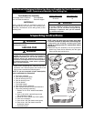
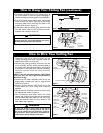
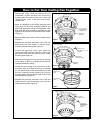
U.L. Model No.: CF905
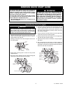
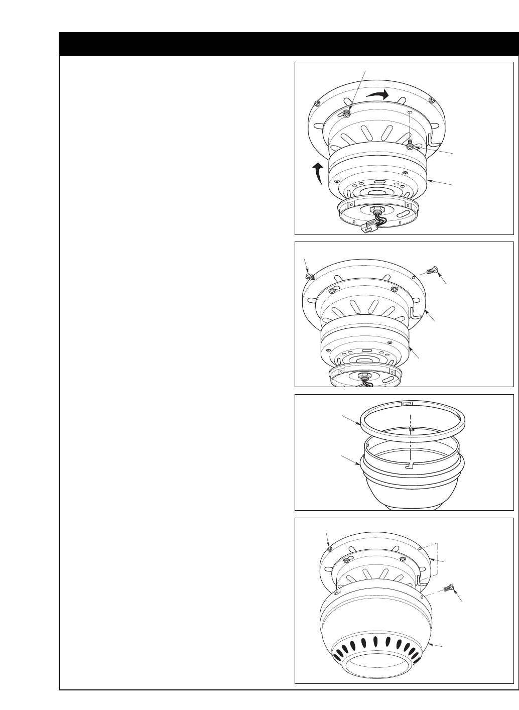
FAN MOTOR
ASSEMBLY
KEY HOLE SLOT
10-24 x 3/8" PAN
HEAD SCREW WITH
LOCKWASHER (3)
Figure 5
1. Remove the 10-24 x 3/8” pan head screw with
lockwasher nearest the hook from the ceiling
mounting plate and retain for later use. Loosen the
remaining two 10-24 x 3/8” pan head screws
several turns.
2. While still attached to the ceiling mounting plate
hook, pivot the fan motor assembly upwards and
mate it up against the ceiling mounting plate. Align
and rotate the motor assembly to engage the two
keyhole slots with the two loosened screw heads
(Figure 5).
3. Securely tighten both 10-24 x 3/8” pan head screws
(Figure 5).
4. Reinstall the previously removed 10-24 x 3/8” pan
head screw with lock washer to lock the motor
assembly onto the ceiling plate (Figure 5).
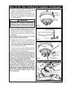
5. Loosen two opposing 10-24 x 3/8” pan head
screws and remove the two remaining 10-24 x 3/8”
pan head screws from the outer rim of the ceiling
mounting plate (Figure 6).
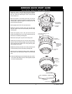
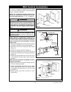
6. Slide the fan housing trim ring over the fan housing
cover (Figure 7). Be sure to position the flat surface
upwards towards the ceiling.
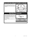
7. Position the fan housing cover over the fan motor
assembly. Align and rotate the housing to engage
the two slotted holes of the fan housing cover with
the two loosened screws heads in the ceiling
mounting plate. Securely tighten both 10-24 x 3/8”
pan head screws (Figure 8).
8. Reinstall the previously removed 10-24 x 3/8” pan
head screws to lock the housing cover onto the
ceiling mounting plate (Figure 8).
How to Put Your Ceiling Fan Together
FAN CEILING
MOUNTING PLATE
FAN MOTOR
ASSEMBLY
REMOVE TWO
OPPOSING 10-24 x 3/8"
SCREWS
LOOSEN TWO OPPOSING
10-24 x 3/8" SCREWS
Figure 6
FAN HOUSING
COVER
FAN CEILING
MOUNTING PLATE
REINSTALL THE
TWO PREVIOUSLY
REMOVED 10-24 x
3/8" PAN HEAD
SCREWS
TIGHTEN TWO OPPOSING 10-24 x 3/8"
PAN HEAD SCREWS
Figure 8
CEILING TRIM
RING
FAN HOUSING
COVER
Figure 7