


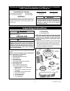
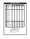
Wall Control Installation
9
U.L. Model No.: CF901
The fan speed control is designed to operate only
one ceiling fan, and not an accessory light kit. This
wall control is rated for 1.2 amps at 120 volts. To
avoid erratic speeds and possible damage to your
ceiling fan, use this control only with the fan pull chain
switch set to its high speed setting.
NOTE: The “0” position is OFF. The four fan
speeds are selected by sliding the bar to the
other four speed positions (“1”, “2”, “3” and “4”).
1. Before disconnecting power, ensure that the fan is
set at the highest speed.
NOTE: Electric connections should be in
accordance with the National Electrical Codes and
all Local Codes. Before starting, disconnect
power to the circuit at the fuse box or circuit
breaker panel.
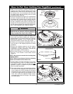
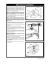
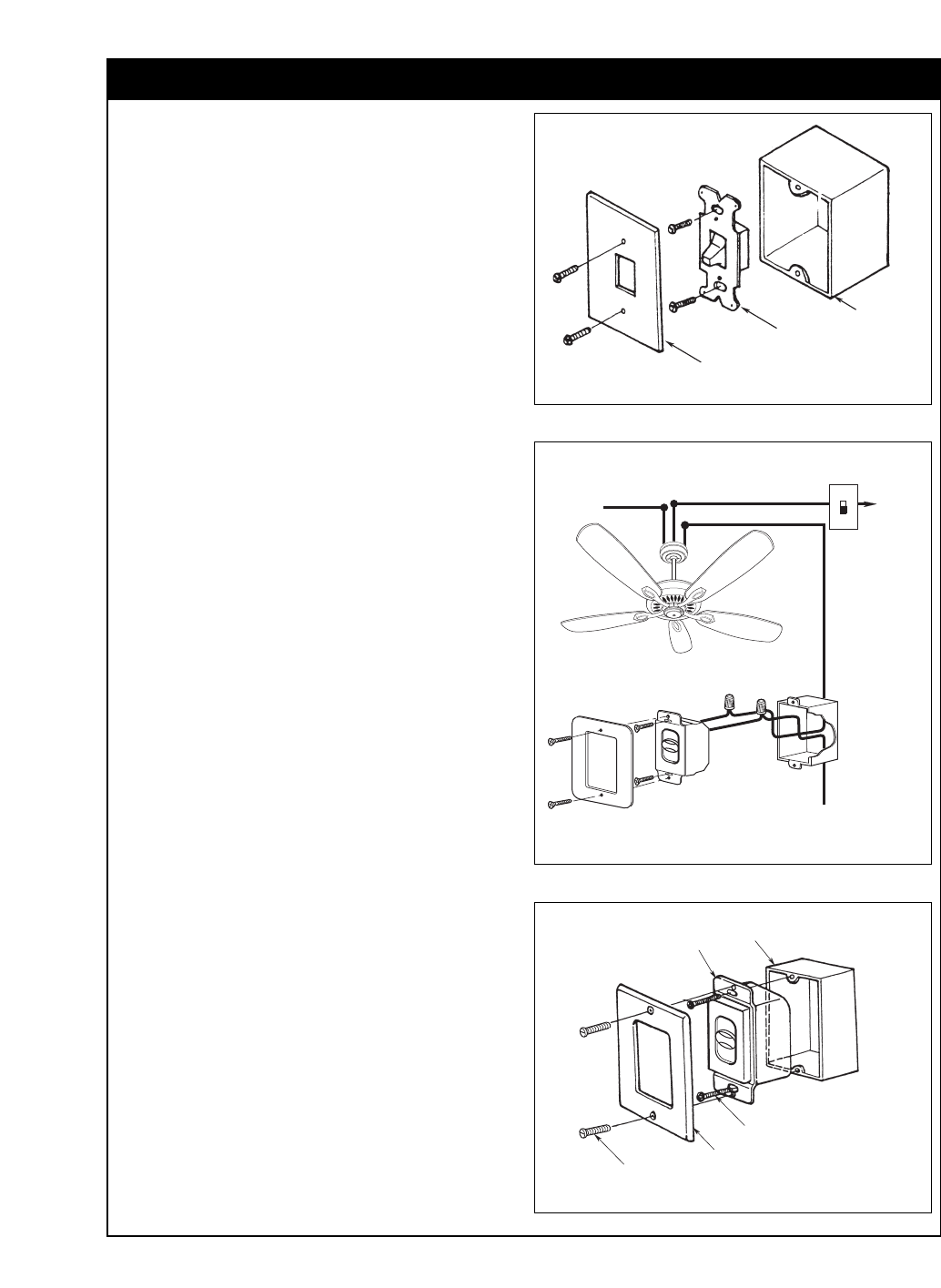
2. Remove the faceplate and screws from the existing
wall switch. Pull switch out from wall outlet box.
3. Disconnect wire from existing fan wall switch
(Figure 14).
4. Slide the fan control in the OFF position (0).
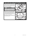
5. Connect one BLACK wire from the fan speed
control to the fan/motor lead with a wire connector
(provided). (Figure 15.)
6. Connect the other BLACK wire from the fan speed
control to the 120VAC hot wire with a wire
connector (provided).
NOTE: Use wire connectors (supplied) to secure
electrical connections.
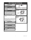
7. Attach the fan speed control to the wall outlet box
with two 6-32 x 3/4” screws (provided).
8. Position the faceplate (provided) onto the speed
control. Using the two 6-32 x 1/4” screws, screw
the faceplate and speed control to the wall outlet
box (Figure 16).
9. Restore power at the main fuse box or circuit
breaker panel.
FACEPLATE
SWITCH
WALL
OUTLET
BOX
Figure 14
6-32 x 1/4" SCREW (2)
FACEPLATE
FAN SPEED
CONTROL
OUTLET BOX
4
0
3
2
1
6-32 x 3/4"
SCREW (2)
Figure 16
MOTOR LOAD
1.2 AMP MAXIMUM
TO 120VAC
SOURCE HOT
BLACK
BLACK
4
0
3
2
1
TO
NEUTRAL
TO FAN MOTOR LOAD
STANDARD ON-OFF
WALL LIGHT SWITCH
TO
120-VOLT
LIGHT
SUPPLY
HOT
TO FAN LIGHT
Figure 15