


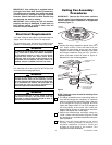

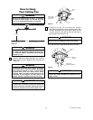
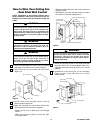
It is critical that the clevis pin in the motor coupling
is properly installed and the setscrew securely
tightened. Failure to verify that the pin and setscrew
are properly installed could result in the fan falling.
WARNING
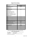
HAIRPIN
CLIP
CLEVIS
PIN
CLEVIS
PIN
SETSCREW (2)
DOWNROD
MOTOR COUPLING
UPPER
SETSCREW
HAIRPIN
CLIP
MOTOR
COUPLING
SETSCREW (2)
CLEVIS PIN
Figure 8
14. Align the clevis pin holes in the downrod with the
holes in the motor coupling. Install the clevis pin
and secure with the hairpin clip (Figure 8). The
clevis pin must go through the holes in the motor
coupling and the holes in the downrod. Be sure to
push the straight leg of the hairpin clip through the
hole near the end of the clevis pin until the curved
portion of the hairpin clip snaps around the clevis
pin. The hairpin clip must be properly installed to
prevent the clevis pin from working loose. Pull on
the downrod to make sure the clevis pin is
properly installed.
15. While pulling up on the downrod, securely tighten
the two setscrews in the motor coupling
(Figure 8).
NOTE: The two setscrews must be properly
installed as described above, or fan wobble could
result.
NOTE: If installing ceiling fan on shorter ceilings
and using the 4.5” downrod, proceed to Step 16
and then onto Step 21.
If installing ceiling fan on a minimum
recommended floor-to-fan clearance for a 9-foot
ceiling using the 10” downrod, proceed to
Step 17.
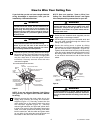
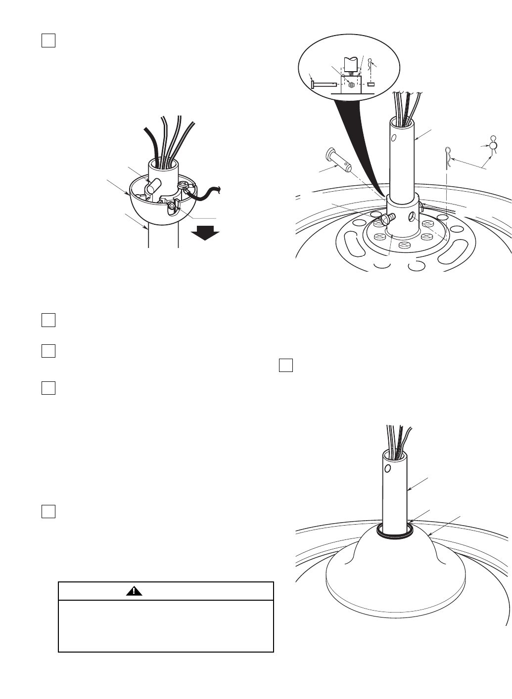
16. 4.5” Downrod Installation: Be sure the grommet
is properly installed in the coupling cover, then
slide the coupling cover on the downrod until it
rests on the motor housing. Be sure that the
coupling cover is oriented correctly (Figure 9).
Proceed to Step 21 to complete assembly.
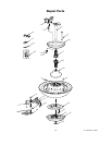
6
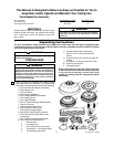
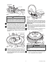
11. Obtain the 10” hanger ball/downrod assembly and
remove the hanger ball by loosening the setscrew
in the hanger ball until the ball falls freely down
the downrod (Figure 7). Remove the pin from the
downrod, then remove the hanger ball. Retain the
pin and hanger ball for reinstallation in Step 22.
Discard the 10” downrod if using the 4.5”
downrod.
NOTE: The longer downrod (10”) furnished with
the ceiling fan provides the minimum
recommended floor-to-fan blade clearance for a 9-
foot ceiling. The 4.5” downrod (supplied) is to be
used for shorter ceilings.
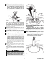
12. Separate, untwist and unkink the black, white and
blue motor 80” motor leads. Route these wires
through the desired downrod.
13. Loosed the two setscrews in the motor coupling.
Slide the downrod down the wires and seat the
downrod in the motor coupling (Figure 8).
PIN
HANGER
BALL
SETSCREW
DOWNROD
Figure 7
U.L. Model No.: CF830U.L. Model No.: CF830
GROMMET
COUPLING COVER
4.5" DOWNROD
Figure 9