


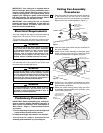
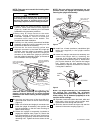
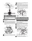

17. Loosen the two setscrews in motor coupling if
necessary. Separate, untwist and unkink the
three 80” motor leads. Route the motor lead
wires through the desired downrod. Align the
clevis pin holes in the downrod with the holes in
the motor coupling. Install the clevis pin and
secure with the hairpin clip (Figure 7). The clevis
pin must go through the holes in the motor
coupling and the holes in the downrod. Be sure to
push the straight leg of the hairpin clip through
the hole near the end of the clevis pin until the
curved portion of the hairpin clip snaps around
the clevis pin. The hairpin clip must be properly
installed to prevent the clevis pin from working
loose. Pull on the downrod to make sure the
clevis pin is properly installed.
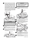
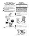
18. While pulling up on the downrod, securely tighten
the two setscrews in the motor coupling
(Figure 8).
NOTE: The two setscrews must be properly
installed as described above, or fan wobble could
result.
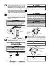
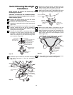
20. 12” Or Optional Longer Downrod Installation
ONLY:
Slide the decorative lower scroll over the
12” downrod to rest upon the fan motor housing
(Figure 9).
DECORATIVE
LOWER SCROLL
UPPER GLASS
SHADE
9" DOWNROD
(or longer)
MOTOR
HOUSING
Figure 9
6
COUPLING COVER
DOWNROD
MOTOR HOUSING
UPPER GLASS
SHADE
Figure 8
21. Position the decorative scroll end over the edge
of the uplight glass shade and slide into one of
the legs of the decorative lower scroll.
22. Assemble the scroll end and lower scroll using the
two screws (supplied). Assemble the remaining
two legs and ends as described (Figure 10).
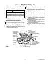
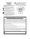
23. Slide the decorative upper scroll over the
downrod engaging the pin of the decorative lower
scroll into one hole of the decorative upper scroll
and secure screw in collar of the decorative
upper scroll (Figure 11).
24. Position the ceiling cover over the downrod. Be
sure the cover is oriented correctly, with the large
opening at the top (Figure 11).
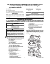
U.L. Model No.: CF820U.L. Model No.: CF820
It is critical that the clevis pin in the motor coupling
is properly installed and the setscrew securely
tightened. Failure to verify that the pin and setscrew
are properly installed could result in the fan falling.
WARNING
IMPORTANT
A. If you have installed the 12” or optional longer
downrod and are planning to install the
decorative scrolls, proceed with Step 20.
B. If you have installed the 6” downrod, skip
Step 20 and continue with Step 24.
DOWNROD
CLEVIS
PIN
UPPER GLASS
SHADE
FAN MOTOR
HOUSING
HAIRPIN
CLIP
SETSCREWS
CLEVIS PIN
MOTOR
COUPLING
DOWNROD
HAIRPIN
CLIP
Figure 7
UPPER GLASS
SHADE
DECORATIVE
SCROLL END
SCREW (2 per
assembly)
DECORATIVE
LOWER SCROLL
DECORATIVE
SCROLL END
EDGE OF
GLASS
Figure 10
19. Be sure the grommet is properly installed in the
coupling cover, then slide the coupling cover on
the downrod until it rests on the motor housing.
Be sure that the coupling cover is oriented
correctly (Figure 8).