5
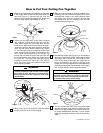
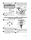
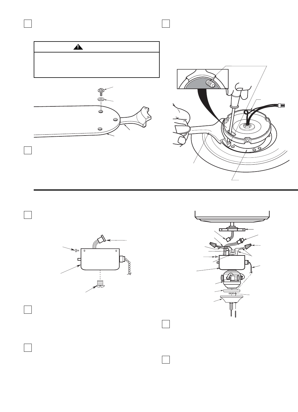
8. Turn the fan assembly upside down in preparation
for mounting the fan blade assemblies.
NOTE: Take care not to scratch fan housing when
installing blades.
BLADE FLANGE
FAN BLADE
M5 x 6 SLOTTED PHILLIPS
WASHER HEAD BLADE
SCREW (3)
BLADE WASHER (3)
Figure 5
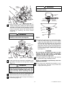
PREASSEMBLED
M6 x 14 FLANGE
SCREWS (2)
(INSTALL
THROUGH SLOT
IN SWITCH
HOUSING PLATE)
BLADE FLANGE
SWITCH HOUSING
PLATE
MOTOR HUB
Figure 6
Installing The Light Fitter And Glass
To reduce the risk of personal injury, do not bend the
blade flange when installing the blade flanges,
balancing the blades or cleaning the fan. Do not
insert foreign objects in between rotating fan blades.
WARNING
9. Rotate the motor hub until the flange screw hole is
visible through the slot in the switch housing plate.
Attach the blade assembly to the motor hub using
the two M6 x 14 flange screws preassembled in
flange. Make sure the screws are tightened
securely (Figure 6). Repeat this procedure for the
other four blade assemblies.
7. Mount blade flanges to fan blades using three
M5 x 6 slotted Phillips washer head blade screws
and three blade washers (Figure 5).
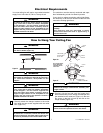
1. Remove the center plug screw from the switch
housing assembly (Figure 7). Remove and retain
the two wire connectors.
SCREWS
SWITCH
CUP
SWITCH CUP
CONNECTOR
CENTER PLUG SCREW
Figure 7
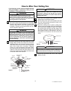
OUTER BOWL
CAP
LOCKWASHER
SCREWS
SWITCH HOUSING PLATE
WIRE
CONNECTORS
WHITE WIRES
BLACK WIRE
FAN SWITCH
CHAIN
HEX NUT
SWITCH
HOUSING ASSEMBLY
SWITCH HOUSING
CONNECTOR
BLUE WIRE
MOTOR CONNECTOR
LIGHT FITTER
METAL SAFETY
CAP
HEX
NUT
Figure 8
2. Remove and retain the lockwasher and nut from
the light fitter. Insert the black and white wires from
the light fitter through the center hole in the switch
housing assembly. Thread the switch housing
assembly onto the light fitter. Reinstall the lock-
washer and nut and tighten securely (Figure 8).
3. Connect the white wire from the ceiling fan to the
white wire of the light fitter. Connect the blue wire
from the ceiling fan to the black wire of the light fit-
ter. Use wire connectors (previously removed) to
make connections (Figure 8).
4. Engage the connector of the switch housing
assembly with the motor connector (Figure 9). The
two connectors are keyed and color-coded and
must be mated correctly (color-to-color) before they
can be engaged. Make sure the connector latch
closes properly.
5. Carefully tuck all wires and splices into the switch
housing.
U.L. Model No.: CF775-2


