


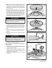
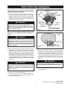
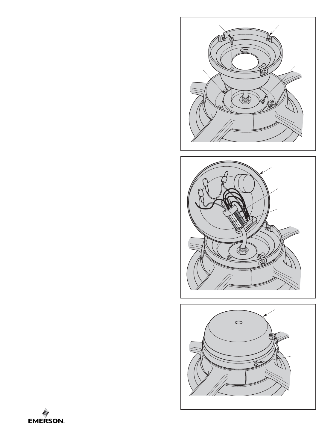
13. Remove one of the screws from the switch adapter.
Retain for future installation. Loosen the two
remaining screws in the switch adapter for
installation of the switch housing cover plate
(Figure 7).
14. Place the switch housing cover plate onto the
switch adapter. Engage the keyholes of the switch
housing cover plate by rotating the switch housing
cover plate clockwise on the switch adapter.
Retighten the two screws and reinstall the screw
previously removed. Tighten all three screws
securely (Figure 7).
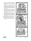
15. Engage the connector of the switch housing
assembly with the motor connector (Figure 8). The
two connectors are keyed and color-coded and
must be mated correctly (color-to-color) before they
can be engaged. Make sure the connector latch
closes properly.
16. Remove the three switch housing screws from the
switch housing cover plate. Position the switch
housing assembly on the switch housing cover
plate and align the holes in the switch housing
assembly with the holes in the plate. Secure the
switch housing assembly by installing the three
screws (Figure 9).
NOTE: Do not pinch wires between the switch
housing assembly and the switch housing plate.
17. You have now completed the assembly of your new
ceiling fan. You can now proceed with hanging and
wiring your fan.
SWITCH HOUSING
ASSEMBLY
SWITCH HOUSING
ASSEMBLY
CONNECTOR
MOTOR HOUSING
CONNECTOR
Figure 8
REMOVE SWITCH
ADAPTER SCREW
SWITCH HOUSING
COVER PLATE
LOOSEN SWITCH
ADAPTER
SCREWS (2)
SWITCH
ADAPTER
Figure 7
SWITCH
HOUSING
ASSEMBLY
SWITCH
HOUSING
SCREW (3)
Figure 9
6
U.L. Model No.: CF772