


5 U.L. Model No.: CF712
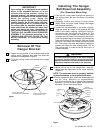
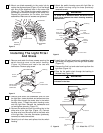
1. Unscrew (but do not remove) the two mounting
screws in the outlet box (Figure 6). Position the
hanger bracket on the outlet box so that the T-slots
in the hanger bracket are aligned with the outlet
box screws.
NOTE: The hanger bracket must be mounted
flush with the ceiling in order for the ceiling cover
to install properly. If necessary, use leveling
washers (not supplied) between the outlet box
and the hanger bracket.
2. Slide the hanger bracket onto the outlet box
screws. Center the bracket over the outlet box and
then securely tighten the screws (Figure 7).
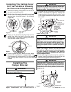
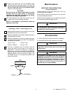
The fan must be hung with at least 7' of clearance
from floor to blades (Figure 5).
WARNING
!
FLOOR
7'
MIN.
Figure 5
HANGER
BRACKET
LOOSEN TWO
SCREWS (SUPPLIED
WITH OUTLET BOX)
OUTLET BOX
SLIDE THE HANGER
BRACKET ONTO
THE OUTLET BOX
SCREWS, THROUGH
THE T-SLOT
T-SLOT
Figure 6
Hanger bracket must seat firmly against outlet box. If
the outlet box is recessed, use leveling washers
between the hanger bracket and the outlet box until
the bracket is flush with the ceiling. If bracket and/or
outlet box are not securely attached, the fan could
wobble or fall.
WARNING
!
The outlet box and joist must be securely mounted and
capable of supporting at least 50 lbs. Use only a U.L.
outlet box listed as “Acceptable for Fan Support”.
WARNING
!
Installing The
Hanger Bracket
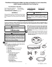
Installing The Ceiling Cover
On The Fan Motor Housing
(For Close-to-the-Ceiling Mounting)
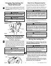
1. Remove and retain three screws from the top of
the motor housing (Figure 3A).
2. Position the rubber gasket (supplied in parts bag)
on the motor housing (small holes in gasket
centered over the screw holes in the housing)
(Figure 3B).
3. Gently pry the decorative cap (Figure 2) from the
ceiling cover. Align the holes in the ceiling cover
with the holes in the motor housing and secure
using the three screws (Figure 4).
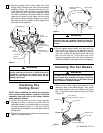
4. The fan comes with blue, black and white leads
that are 42” long. Measure up approximately 6 to
9-inches above the motor coupling. Cut off excess
leads and strip back insulation 1/2-inch from ends
of leads.
REMOVE SCREWS (3)
INSTALL GASKET
Figure 3A
Figure 3B
SCREW (3)
RUBBER
GASKET
Figure 4
To reduce the risk of fire, electrical shock, or personal
injury, mount fan to outlet box marked “Acceptable for
Fan Support”, and use screws supplied with outlet box.
Most outlet boxes commonly used for support of light
fixtures are not acceptable for fan support and may
need to be replaced. Consult a qualified electrician if
in doubt.
WARNING
!
HANGER BRACKET
HOOK
SECURELY
TIGHTEN
SCREWS
Figure 7