


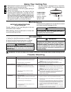
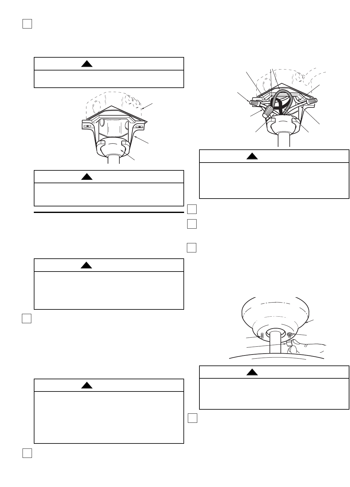
5. Secure the ceiling cover in place by sliding lockwash-
ers over the threaded studs and installing the two
knurled knobs (supplied). (Figure 10.) Tighten the
knurled knobs securely until the ceiling cover fits
snugly against the ceiling and the hole in the ceiling
cover is clear of the downrod. Your fan is now wired to
be turned on and off from the fan switch.
6. Cut the 3-speed switch pull chain to a desired length
(optional). Connect the wood pendant (supplied) to
the 3-speed switch pull chain by sliding the wooden
pendant (small hole first) onto the pull chain. Attach
the chain coupler to the end of the chain and allow
the wooden pendant to fall down over the coupling.
6
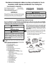
How to Wire Your Ceiling Fan
OUTLET
BOX
HANGER
BRACKET
HANGER BALL/
DOWNROD ASSEMBLY
Figure 3
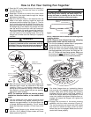
NOTE: CEILING COVER,
SUPPLY WIRES AND
FAN WIRES OMITTED
FOR CLARITY.
Figure 8
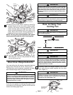
2. Carefully lift the fan and seat the hanger ball/
downrod assembly on the hanger bracket that was
just attached to the outlet box (Figure 8). Be sure
the groove in the ball is lined up with tab on the
hanger bracket (Figure 7).
If you feel that you do not have enough electrical
wiring knowledge or experience, have your fan
installed by a licensed electrician.
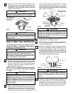
1. Connect the green grounding lead from the hanger
ball and the green grounding lead from the hanger
bracket to the grounding conductor of supply (this
may be a bare wire or wire with green colored
insulation). Securely connect wires with wire con-
nectors supplied. (Figure 9.)
NOTE: If you are using an Emerson Light Fixture
with your fan, see Light Fixture Owner’s Manual
for wiring.
2. Securely connect the fan motor white wire to the
supply white (neutral) wire using wire connector
supplied (Figure 9). Securely connect the fan
motor black wire and blue wire to the supply black
(hot) wire using wire connector supplied (Figure 9).
After connections have been made, turn leads
upward and carefully push leads into the outlet
box, with the white and green leads on one side of
the outlet box and the black and blue leads on the
other side of the outlet box.
GROUND
WIRE
LISTED
WIRE
CONNECTOR (3)
GREEN WIRE
(GROUND) FROM
HANGER BRACKET
GREEN WIRE
(GROUND) FROM
HANGER BALL
WHITE SUPPLY
(NEUTRAL)
WHITE FAN
WIRE
BLACK SUPPLY
(HOT)
BLACK AND BLUE
FAN WIRES
Figure 9
NOTE: CEILING COVER
OMITTED FOR CLARITY.
CEILING COVER
THREADED STUD
KNURLED KNOB
LOCKWASHER
3. Screw the two threaded studs (supplied) into the
tapped holes in the hanger bracket.
4. Lift the ceiling cover up to the threaded studs and
turn until studs protrude through the holes in the
ceiling cover (Figure 10).
Figure 10
Failure to seat tab in groove could cause damage to
electrical wires and possible shock or fire hazard.
WARNING
!
This product is designed to use only those parts
supplied with this product and/or any accessories
designated specifically for use with this product by
Emerson Company. Substitution of parts or acces-
sories not designated for use with this product by
Emerson Company could result in personal injury or
property damage.
WARNING
!
To avoid possible electrical shock, be sure electricity
is turned off at the main fuse box before wiring.
NOTE: If you are not sure if the outlet box is ground-
ed, contact a licensed electrician for advice, as it
must be grounded for safe operation.
To avoid possible fire or shock, do not pinch wires
between the hanger ball/downrod assembly and
hanger bracket.
WARNING
!
WARNING
!
Check to see that all connections are tight, including
ground, and that no bare wire is visible at the wire
connectors, except for the ground wire. Do not
operate fan until blades are in place. Noise and fan
damage could result.
WARNING
!
To avoid possible fire or shock, make sure that the
electrical wires are completely inside the outlet box
and not pinched between the ceiling cover and the
ceiling.
WARNING
!