


NOTE: Take care not to scratch fan housing when
installing blades.
NOTE: Remove and discard the four shipping
spacers and screws from the motor hub.
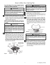
7. Turn the fan assembly upside down in preparation
for mounting the fan blade assemblies.
8. Rotate the motor hub until the flange screw hole is
next to the cutout in the switch housing plate.
Attach the blade assembly to the motor hub using
the two M6 x 14 flange screws preassembled in
flange (Figure 3). Make sure all screws are tight-
ened. Repeat this procedure for the other four
blade assemblies.
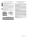
9. The blade flanges have an interlocking feature
that must be fully engaged before tightening the
screws. Make sure all the flanges are properly
engaged and then tighten the flange screws. If
one of the flanges does not seat properly on the
motor hub, loosen the adjacent flange screws, re-
engage and reseat the flanges, then tighten the
screws again.
10. Engage the connector of the switch housing
assembly with the motor connector (Figure 4).
The two connectors are keyed and color-coded
and must be mated correctly (color-to-color)
before they can be engaged. Make sure the con-
nector latch closes properly.
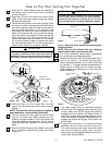
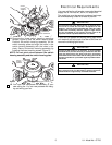
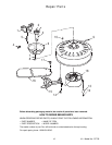
1. Pass the 42” motor leads through the opening in
the ceiling cover. Be sure the cover is oriented
correctly (Figure 1).
2. Separate, untwist and unkink the three motor
leads. Route the motor leads through the hanger
ball/downrod assembly.
3. Loosen the two screws in the motor coupling. Align
the clevis pin holes in the downrod with the holes in
the motor coupling. Install the clevis pin and secure
with the hairpin clip (Figure 1). The clevis pin must
go through the holes in the motor coupling and the
holes in the downrod. Be sure to push the straight
leg of the hairpin clip through the hole near the end
of the clevis pin until the curved portion of the
hairpin clip snaps around the clevis pin. The hairpin
clip must be properly installed to prevent the clevis
pin from working loose. Pull on the hanger ball to
make sure the clevis pin is properly installed.
4. While pulling up on the hanger ball, securely
tighten the two setscrews in the motor coupling
(Figure 1).
NOTE: The setscrew must be properly installed as
described above, or fan wobble could result.
5. The fan comes with blue, black and white leads
that are 42-inches long. Before installing the fan,
measure up approximately 6 to 9-inches above top
of hanger ball/downrod assembly. Cut off excess
leads and strip back insulation 1/2-inch from end of
leads.
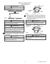
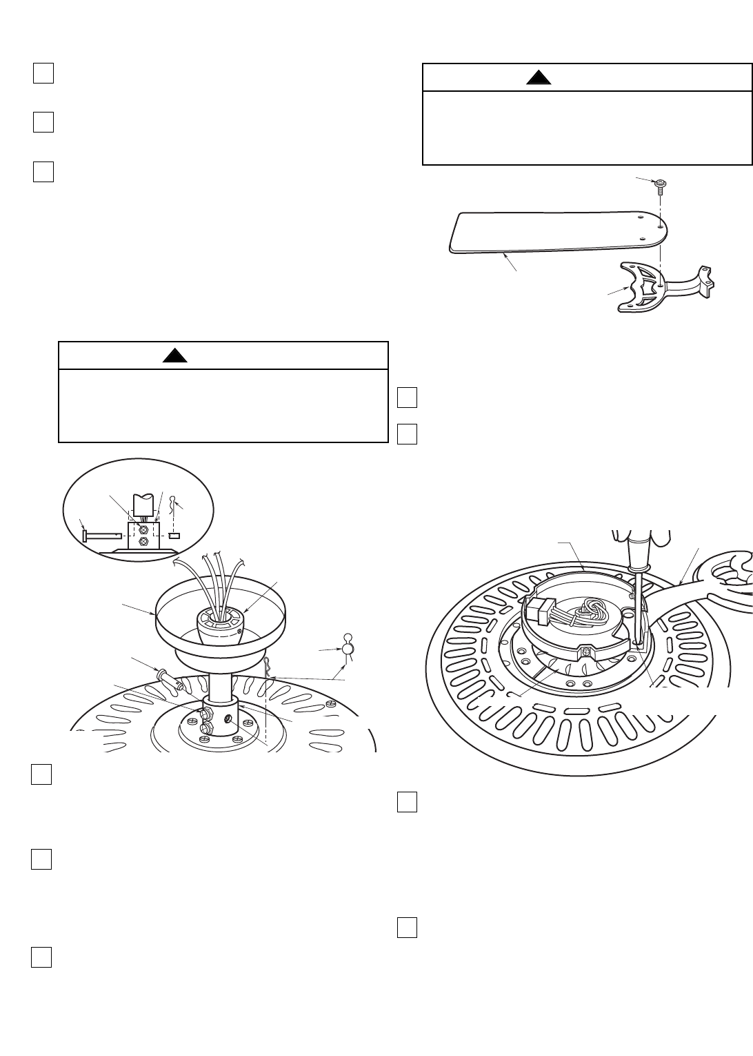
6. Mount the blade flanges to fan blades using three
M5 x 6 washer head blade screws per blade
(Figure 2).
4 U.L. Model No.: CF705
How to Put Your Ceiling Fan Together
CEILING
COVER
CLEVIS
PIN
HAIRPIN
CLIP
CLEVIS
PIN
HANGER BALL/
DOWNROD ASSEMBLY
M5x10
SETSCREWS
MOTOR COUPLING
MOTOR
COUPLING
HAIRPIN
CLIP
M5x10
SETSCREWS
CLEVISPIN
Figure 1
FAN BLADE
BLADE FLANGE
M5x6WASHER HEAD BLADE
SCREW (3)
Figure 2
SWITCH HOUSING
PLATE
MOTOR HUB
PREASSEMBLED M6x 14
FLANGE SCREWS(2)
BLADE FLANGE
Figure 3
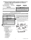
It is critical that the clevis pin in the motor coupling
is properly installed and the setscrews securely
tightened. Failure to verify that the pin and setscrews
are properly installed could result in the fan falling.
WARNING
!
To reduce the risk of personal injury, do not bend the
blade flange when installing the blade flanges,
balancing the blades or cleaning the fan. Do not
insert foreign objects in between rotating fan blades.
WARNING
!