


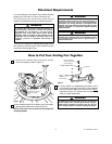
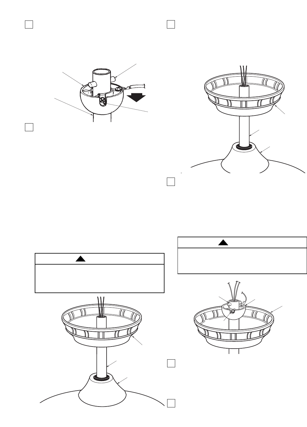
CEILING
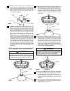
COVER
HANGER BALL
PIN
SETSCREW
Figure 10
It is critical that the pin in the hanger ball is properly
installed and the setscrew securely tightened.
Failure to verify that the pin and setscrew are
properly installed could result in the fan falling.
WARNING
!
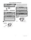
16. The fan comes with blue, black and white leads
that are 80” long. Before installing fan, measure
up approximately 6 to 9-inches above top of
hanger ball/downrod assembly. Cut off excess
leads and strip back insulation 1/2-inch from end
of leads.
17. You have now completed the assembly of your
new ceiling fan. You can now proceed with
hanging and wiring your fan.
14. Make sure the grommet is properly installed in
the coupling cover, then slide the coupling cover
on the downrod until it rests on the motor
housing. Place the ceiling cover over the
downrod. Be sure that the ceiling cover and the
coupling cover are both oriented correctly
(Figure 9).
6
It is critical that the clevis pin in the motor coupling
is properly installed and the setscrews securely
tightened. Failure to verify that the pin and setscrews
are properly installed could result in the fan falling.
WARNING
!
DOWNROD
CEILING
COVER
COUPLING COVER
Figure 8
DOWNROD
CEILING
COVER
COUPLING COVER
Figure 9
NOTE: The setscrews must be properly installed
as described above, or fan wobble could result.
15. Reinstall the hanger ball (Figure 10) on the
downrod as follows. Route the three 80” motor
leads through the hanger ball. Position the pin
through the two holes in the downrod and align
the hanger ball so the pin is captured in the
groove in the top of the hanger ball. Pull the
hanger ball up tight against the pin and securely
tighten the setscrew in the hanger ball. A loose
setscrew could create fan wobble.
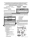
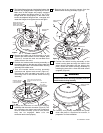
12. Remove the hanger ball by loosening the
setscrew in the hanger ball until the ball falls
freely down the downrod (Figure 7). Remove the
pin from the downrod, then remove the hanger
ball. Retain the pin and hanger ball for
reinstallation in Step 15.
13. Separate, untwist and unkink the three 80” motor
leads. Route the motor lead wires through the
downrod. Remove the upper setscrew from the
motor coupling. Align the clevis pin holes in the
downrod with the holes in the motor coupling.
Install the clevis pin and secure with the hairpin
clip (Figure 8). The clevis pin must go through the
holes in the motor coupling and the holes in the
downrod. Be sure to push the straight leg of the
hairpin clip through the hole near the end of the
clevis pin until the curved portion of the hairpin
clip snaps around the clevis pin. The hairpin clip
must be properly installed to prevent the clevis pin
from working loose. Pull on the downrod to make
sure the clevis pin is properly installed. Reinstall
the upper setscrew in the motor coupling. Check
that the lower setscrew is tightened securely
(Figure 8).
PIN
SETSCREW
HANGER
BALL
DOWNROD
Figure 7